

Motor device having transmission member that is movable relative to motor side coupling part and worm gear side coupling part
- Summary
- Abstract
- Description
- Claims
- Application Information
AI Technical Summary
Benefits of technology
Problems solved by technology
Method used
Image

Examples
first embodiment
[First Embodiment]
(Entire Structure)
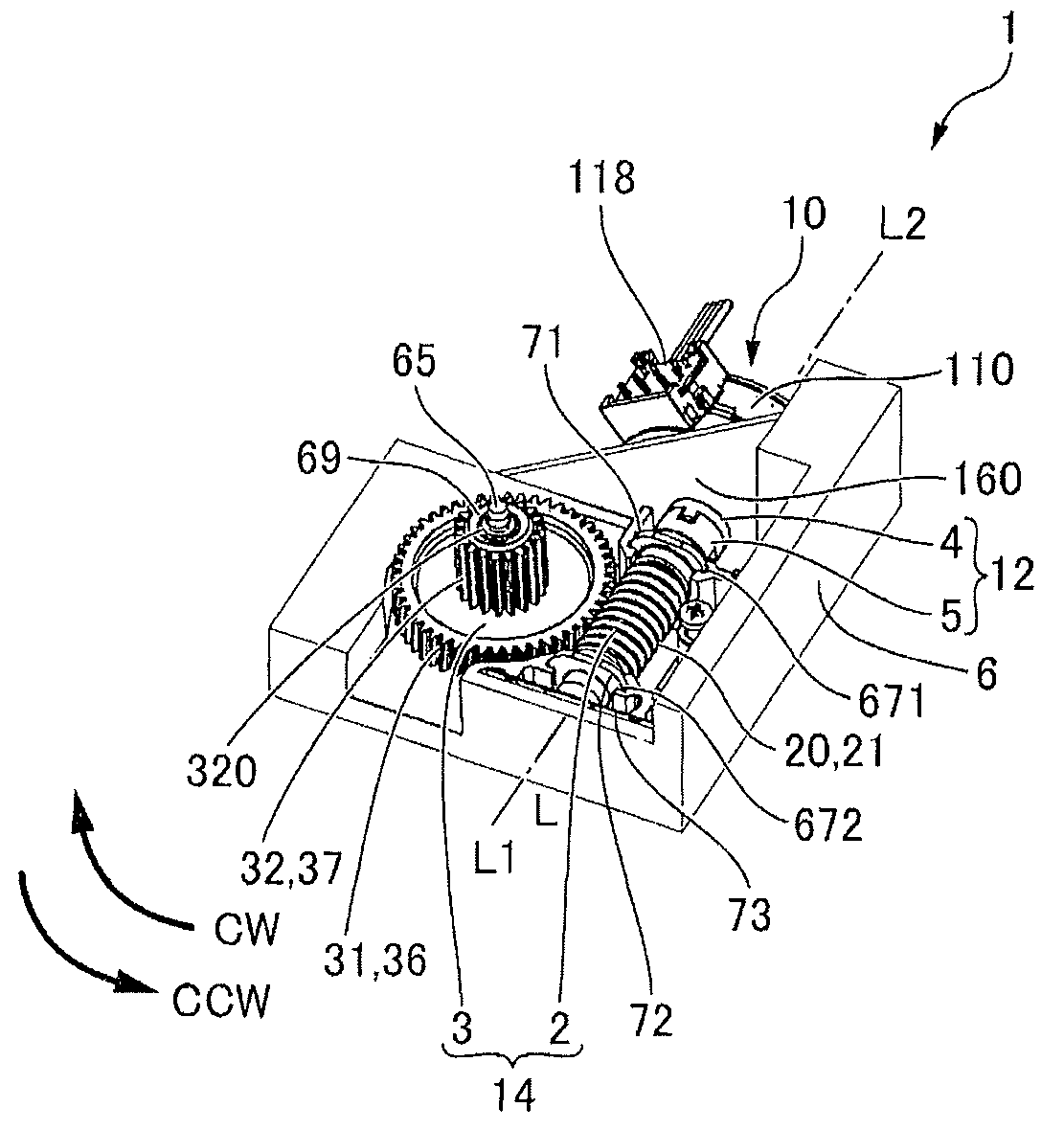
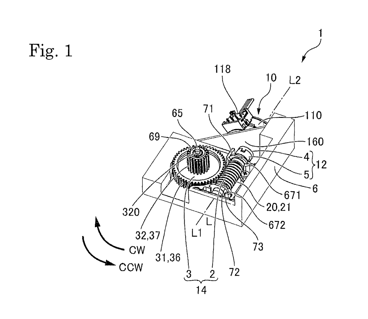
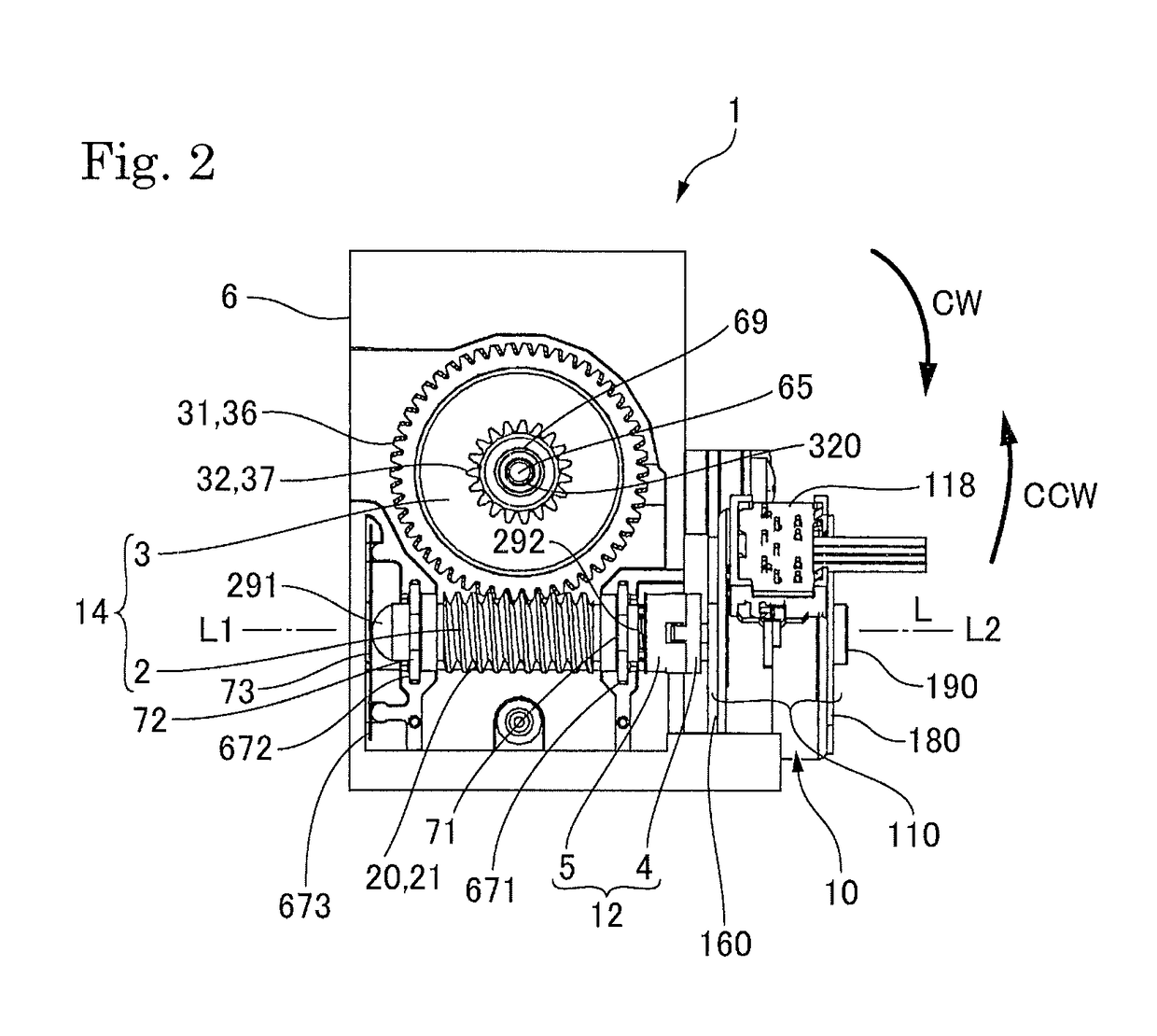
[0031]FIG. 1 is a perspective view showing a motor device in accordance with a first embodiment of the present invention. FIG. 2 is a plan view showing the motor device in accordance with the first embodiment of the present invention.
[0032]A motor device 1 shown in FIGS. 1 and 2 includes a motor 10 as a drive source, a gear mechanism 14 for transmitting rotation of the motor 10, a moved member (not shown) to which rotation of the motor 10 is transmitted through the gear mechanism 14, and a frame 6 on which the motor 10, the gear mechanism 14, the moved member and the like are mounted. The motor device 1 moves a driven member or the like which is mounted on or connected with the moved member.
[0033]The gear mechanism 14 includes a worm gear 2 to which rotation of the motor 10 is transmitted and a worm wheel 3 which is engaged with the worm gear 2. A spiral groove 21 is formed on an outer peripheral face 20 of the worm gear 2 and a teeth part 36 enga...
second embodiment
[Second Embodiment]
[0075]FIG. 7 is an explanatory view showing a motor device 1 in accordance with a second embodiment of the present invention. Basic structures of the second embodiment and embodiments described below are similar to the first embodiment and thus the same reference signs are used in common portions and their descriptions are omitted.
[0076]As shown in FIG. 7, a motor device 1 in the second embodiment includes a side pressure application mechanism 7 for generating side pressure “F” which presses the worm gear 2 toward an opposite side to a side where the worm wheel 3 is located. Therefore, the worm gear 2 and the worm wheel 3 can be appropriately engaged with each other.
[0077]In this embodiment, the side pressure application mechanism 7 is provided at the end part 291 of the worm gear 2 on an opposite side to the motor main body 110 side. More specifically, the end part 291 of the worm gear 2 is formed in a hemisphere face and the side pressure application mechanism 7...
third embodiment
[Third Embodiment]
[0079]FIG. 8 is an explanatory view showing a motor device 1 in accordance with a third embodiment of the present invention. As shown in FIG. 8, in the third embodiment, when the worm gear 2 is viewed in the radial direction, the spring receiving face 230 is located on the motor main body 110 side relative to a range where the spiral groove 21 and the worm wheel 3 are engaged with each other. Therefore, when the worm gear 2 is viewed in the radial direction, the spring arrangement hole 23 is not overlapped with the range “W0” where the spiral groove 21 and the worm wheel 3 are engaged with each other. Accordingly, rigidity of a portion of the worm gear 2 where the spiral groove 21 and the worm wheel 3 are engaged with each other is increased.
[0080]In this embodiment, in two radial bearings 71 and 72 (worm gear side radial bearing), the radial bearing 71 located on the motor main body side is further separated from the region “W1” where the spiral groove 21 is forme...
PUM
 Abstract
Description
Claims
Application Information