Mirror drive device capable of high-speed driving and image pickup apparatus

Active Publication Date: 2017-06-15
CANON KK
View PDF1 Cites 0 Cited by
  • Summary
  • Abstract
  • Description
  • Claims
  • Application Information

AI Technical Summary

Benefits of technology

[0008]The present invention provides a mirror drive device and an image pickup apparatus which make it possible to achieve lowered torque and increased speed in mirror drivi

Problems solved by technology

However, if the spring force of the toggle spring is increased, the mirror unit reaches the mirror-down position or the mirror-up position at the increased turning speed of the sub mirror and the main mirror, which causes a large bounce

Method used


Image

  • Mirror drive device capable of high-speed driving and image pickup apparatus
  • Mirror drive device capable of high-speed driving and image pickup apparatus
  • Mirror drive device capable of high-speed driving and image pickup apparatus

Examples


Example

[0043]The present invention will now be described in detail below with reference to the accompanying drawings showing embodiments thereof.

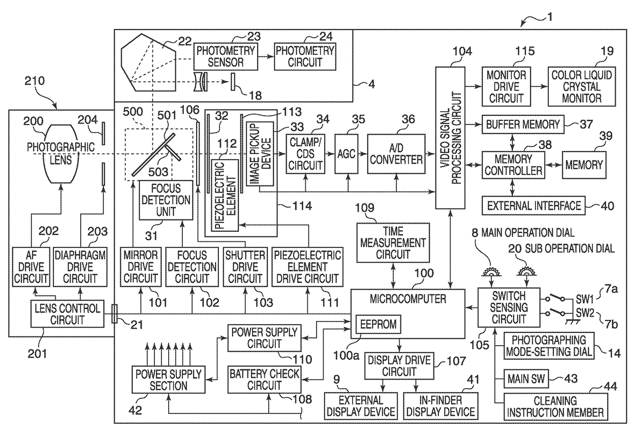
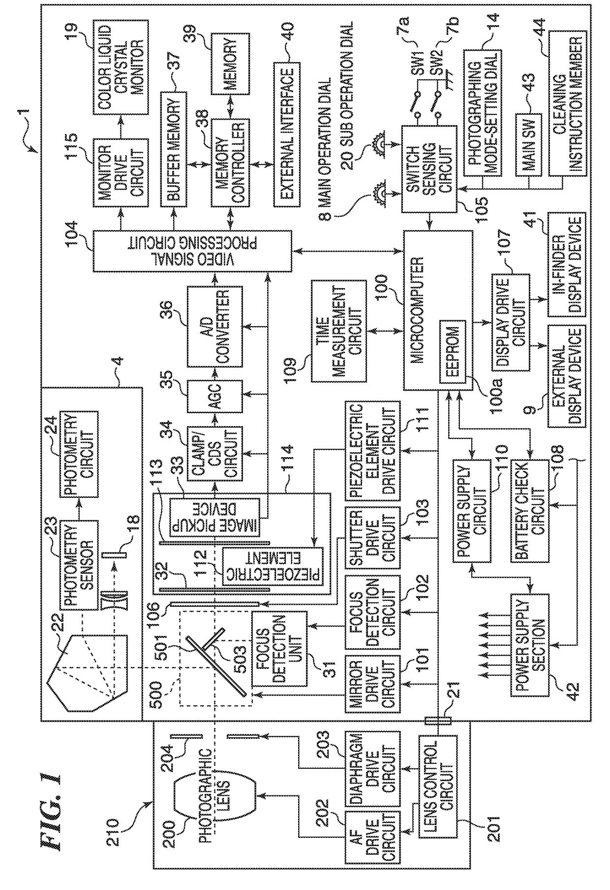
[0044]FIG. 1 is a block diagram of the system configuration of a digital single-lens reflex camera which is an image pickup apparatus equipped with a mirror drive device according to an embodiment of the present invention

[0045]Referring to FIG. 1, in the digital single-lens reflex camera (hereinafter referred to as the camera) according to the present embodiment, an interchangeable lens unit 210 is mounted on a camera body 1 via a mount contact portion 21 in a removable manner.

[0046]First, a description will be given of the camera body 1. In FIG. 1, a microcomputer 100 (hereinafter referred to as the MPU 100) controls the overall operation of the camera. An EEPROM 100a incorporated in the MPG 100 stores time information of a time measurement circuit 109, control programs, and other information items. To the MPU 100, there are connected a mirror dr...


PUM


Abstract

A mirror drive device capable of achieving lower torque and higher speed in mirror driving without necessitating reversing of an urging direction of an urging member during the mirror driving and improve durability thereof at the same time. A main mirror holder holding a main mirror is movable between a mirror-down position is a photographing optical path and a mirror-up position retracted from the photographing optical path. A sub mirror holder holding a sub mirror and rotatably attached to the main mirror bolder is movable between a mirror-down position and a mirror-up position. The sub mirror holder is moved by a driving member from the mirror-down position to the mirror-up position, whereby the main mirror holder is moved from the mirror-down position to the mirror-up position.

Description

BACKGROUND OF THE INVENTION[0001]Field of the Invention[0002]The present invention relates to a mirror drive device equipped with a mechanism for high-speed driving of a mirror unit provided in an image pickup apparatus, such as a single-lens reflex camera, and an image pickup apparatus equipped with the mirror drive device.[0003]Description of the Related Art[0004]In a quick return mirror mechanism e.g. of a single-lens reflex camera, a mirror unit provided with a main mirror and a sub mirror is moved at high speed between a mirror-down position in which the mirror unit enters a photographing optical path and a mirror-up position in which the mirror unit is retracted from the photographing optical path. Each of the mirrors of the mirror unit is brought into contact with a stopper formed in a mirror box, at the mirror-down position, thereby being held in a predetermined stop position, to guide an object light flux having passed through a photographic optical system of the lens unit ...

Claims


Application Information

Patent Timeline
IPC IPC(8): G02B7/182G02B5/20H04N5/225G02B7/08
CPCG02B7/1821H04N5/2254G02B5/208G02B7/08G02B7/28H04N23/672H04N23/55
Inventor MORITA, KEISUKEYAMANA, KAZUAKI
Owner CANON KK
Why Eureka
Try Eureka