
Diverter valve

Inactive Publication Date: 2007-08-30
AMERIKAM
View PDF12 Cites 14 Cited by
  • Summary
  • Abstract
  • Description
  • Claims
  • Application Information

AI Technical Summary

Benefits of technology

[0011] In another aspect of the invention, the diverter valve has the flow passages in the housing and the accessory case configured and oriented to substantially balance hydraulic pressures acting on the ceramic plates. In one embodiment, a flow passage in the housing is open to and parallel with the first ceramic plate whereby pressure in the flow passage can act against the first ceramic plate to urge it toward the second ceramic plate.
[0012] In a further aspect of the invention, the diverter valve in

Problems solved by technology

Normally, balancing the stack up pressure and torque is not a problem with these solutions, but in a valve with complex flows through the disks, e.g. a diverter valve, it has been found that uneven hydraulic pressures on the disks tend to cause leaks.
Moreover, risk of leaks and higher costs attend existing diverter valves where flow must be directed from the rotatable ceramic through a lower housing.

Method used


Image

  • Diverter valve
  • Diverter valve
  • Diverter valve

Examples


Embodiment Construction

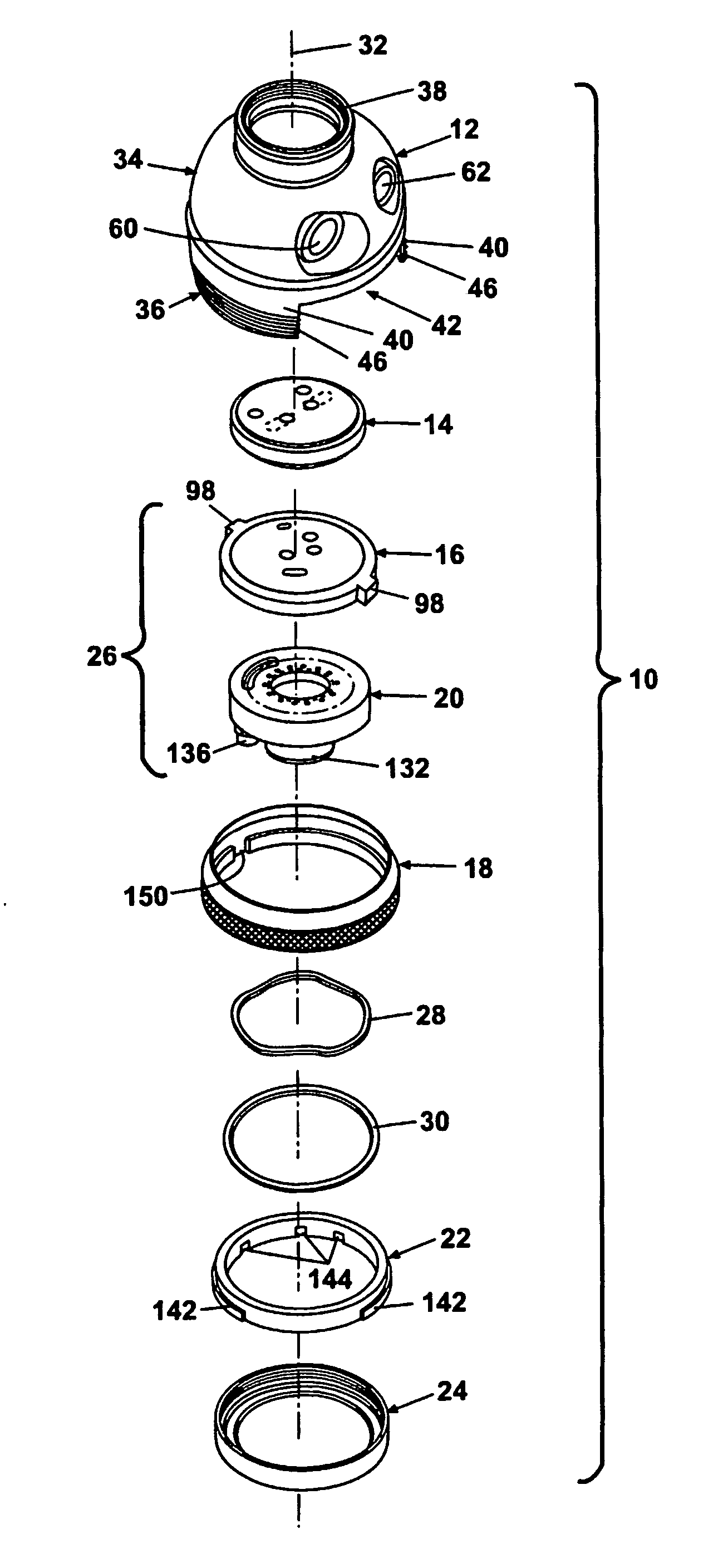
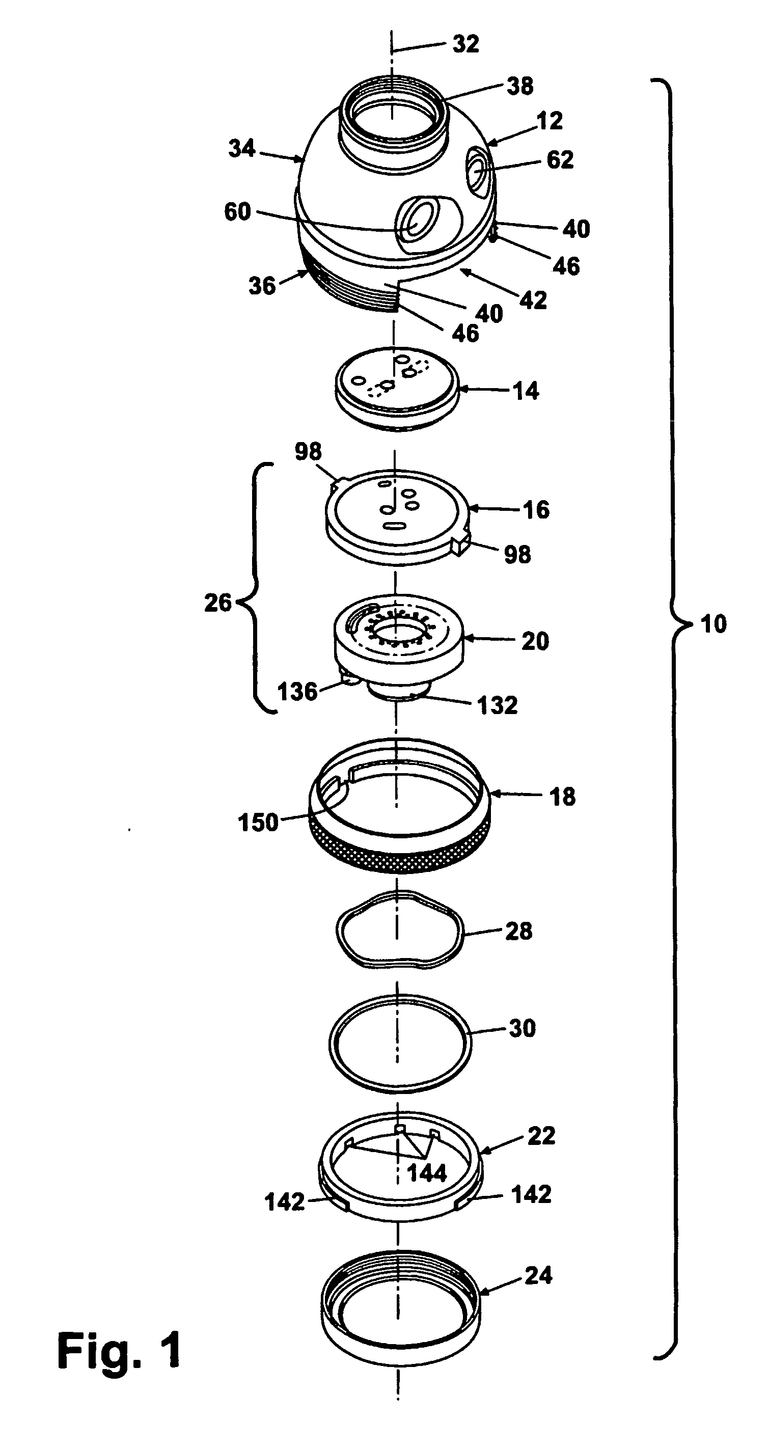
[0038]FIG. 1 illustrates a valve 10 according to the invention. The valve 10 comprises basically a housing 12, a fixed ceramic plate or disk 14, and a rotating ceramic plate or disk 16, the rotation of which is controlled by a selection ring 18, an accessory mount 20, a detent case 22, and a retainer 24. As will be described in further detail later, the fixed ceramic disk 14 is fixed to the housing 12 against rotational movement, and the accessory mount 20 is adhered to the rotating ceramic disk 16. For convenience, the rotating ceramic disk / accessory mount assembly will sometimes be referred to as an outlet assembly 26. The retainer 24 retains the outlet assembly 26, the detent case 22, and the selection ring 18 in the housing 12. A wave spring 28 and a washer 30 facilitate sealing the valve and constitute a thrust bearing that maintains the rotating ceramic disk 16 against the fixed ceramic disk 14 while minimizing torque when the rotating ceramic disk 16 is rotated. It will be ap...


PUM


Abstract

A diverter valve (10) for selectively controlling the flow of fluid from a fluid source to one of several fluid outlets (132, 136) includes a fixed ceramic disk (14) fixed to a housing (12) and a rotating ceramic disk (16) retained in the housing against the fixed disk by a retainer (24). An accessory mount (20) is adhered to the rotating ceramic disk to facilitate connection to accessories and to direct fluid from the valve. Flow passages (88, 90, 104, 106, 108, 110, 112) in the disks cooperate with flow passages (54, 64, 66, 68) in the housing and flow passages (116, 118, 122) in the accessory mount to balance the pressure of fluid flow within the valve against the disks to minimize leaks and prolong durability.

Description

CROSS REFERENCES TO RELATED APPLICATIONS [0001] This application claims the benefits of U.S. application ser. No. 60 / 481,499, filed Oct. 10, 2003, and U.S. application Ser. No. 60 / 481,890, filed Jan. 13, 2004.BACKGROUND OF THE INVENTION [0002] 1. Field of the Invention [0003] The invention relates to a diverter valve that selectively diverts water from a conventional kitchen faucet to one of two or more outlets, and more particularly, to a diverter valve having ceramic disk elements. [0004] 2. Description of the Related Art [0005] Fluid valves using ceramic valve stacks comprising a fixed ceramic disk and a rotating ceramic disk, both of which have pass-through openings to control the flow of fluid through the valve by selective movement of the rotatable ceramic disk, are well known. They typically appear in various configurations, such as in-line valves, conventional faucets, diverter valves, and hydrants, to name a few. Almost all ceramic valves comprise a “stack-up” that traditio...

Claims


Application Information

Patent Timeline
IPC IPC(8): F16K11/078F16K3/10F16K11/074
CPCF16K11/074F16K3/10Y10T137/86815Y10T137/86863Y10T137/9464
Inventor CRESWELL, ROBERT S.ZOLNIEREK, MICHAELREGELBRUGGE, MICHAEL W.CHRYSLER, JIMMIE D.
Owner AMERIKAM
Features
  • Generate Ideas
  • Intellectual Property
  • Life Sciences
  • Materials
  • Tech Scout
  • Unparalleled Data Quality
  • Higher Quality Content
  • 60% Fewer Hallucinations
Learn More