Vehicle seat

a seat frame and seat technology, applied in the field of seat frames, can solve the problems of excessive deformation, receding deformation on the inner side, and breakage on the outer side, and achieve the effect of preventing excessive deformation of the seat frame and good balan

Inactive Publication Date: 2018-04-10
TOYOTA BOSHOKU KK
View PDF16 Cites 2 Cited by
  • Summary
  • Abstract
  • Description
  • Claims
  • Application Information

AI Technical Summary

Benefits of technology

[0006]In the meantime, in a case of this type of a seat frame, when the seat frame is deformed (bent) into an arch shape, a stress in an extension direction is applied to an outer side of this member and a stress in a contraction direction is applied to an inner side thereof (a circumference length difference occurs). From the viewpoint of improving durability of a seat, relatively hard metal tends to be used for the seat frame (as a material thereof). Accordingly, in the configuration of the technique as known in the art, as the seat frame becomes harder, excessive deformation (recessing deformation on the inner side and breakage on the outer side) may occur due to the circumference length difference. The present invention provides a vehicle seat that can prevent excessive deformation of a seat frame as much as possible.
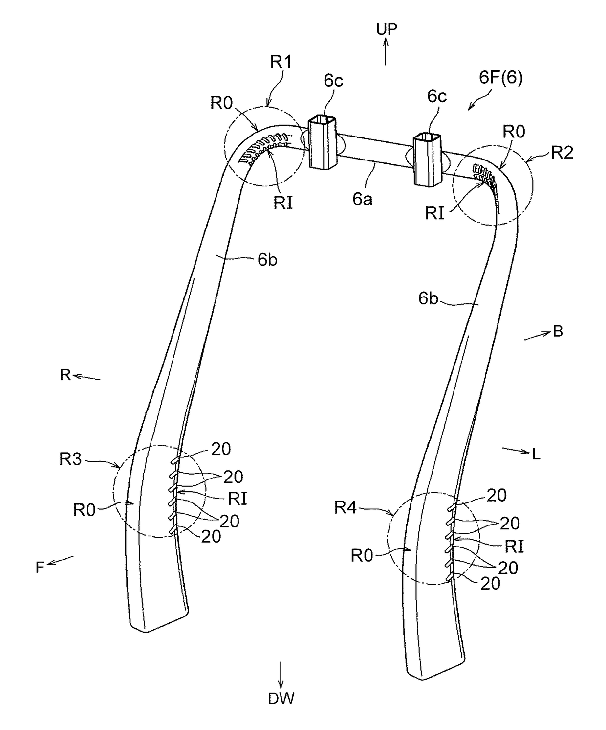
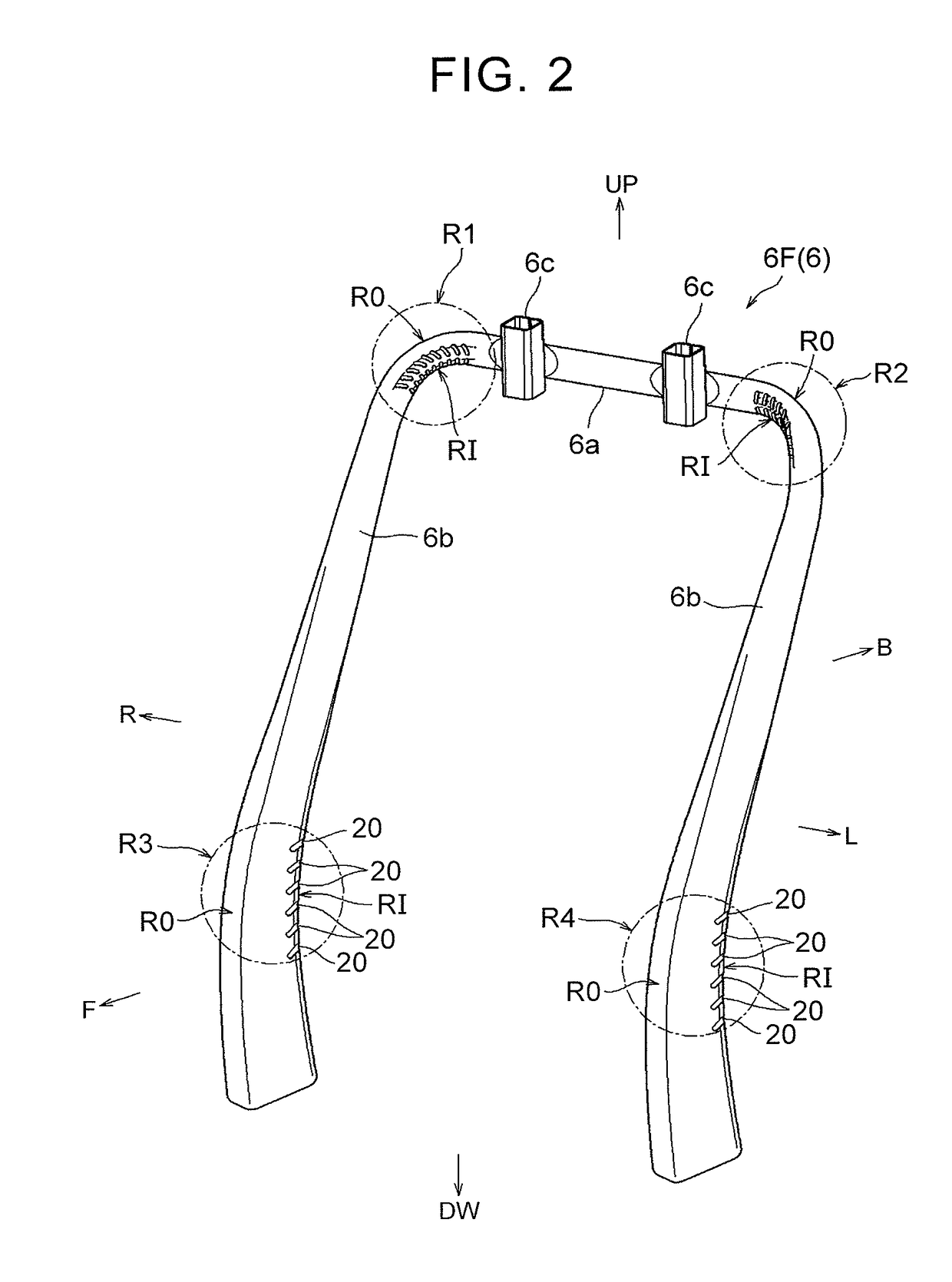
[0008]In the present aspect, the deformable portion has a linear separation portion formed in a projecting manner relative to the recessed portions and extending on the inner side of the deformable portion, and a plurality of recessed portions is formed on each of one side and the other side of the separation portion so as to sandwich the separation portion and placed independently from each other such that adjacent recessed portions are not connected to each other. In the present aspect, the recessed portions are formed independently across the separation portion so as not to become excessively large. By preferably preventing a strong stress from being applied to only a specific recessed portion as such, the deformable portion of the seat frame can be bent while the recessed portions are recessed as equally as possible.
[0009]In the above aspect, each of the recessed portions may have a shape gradually inclined in a direction to be distanced from one end of the seat frame to the other end thereof in the deformable portion. In the above configuration, the shape of each of the recessed portions is a shape that follows a stress distribution to occur on an inner side of the deformable portion at the time of bending the deformable portion. Hereby, the deformable portion can be bent while the recessed portions are recessed smoothly.
[0010]In the above aspect, the recessed portions placed on the one side of the separation portion and the recessed portions placed on the other side of the separation portion may be placed in a symmetric manner across the separation portion. In the above configuration, the recessed portions on the one side and the recessed portions on the other side are placed in a symmetric manner across the separation portion, so that the deformable portion can be bent in a good balance with the recessed portions on both sides being taken as base points.
[0012]According to the above aspect, it is possible to prevent excessive deformation of the seat frame as much as possible. Further, according to the above configuration, the deformable portion of the seat frame can be bent while the recessed portions are recessed smoothly and equally. Further, according to another configuration, the deformable portion of the seat frame can be bent in a good balance. According to further another configuration, it is possible to preferably avoid each of the recessed portions from being connected to another recessed portion adjacent thereto on the tip end side formed with a narrow width.

Problems solved by technology

Accordingly, in the configuration of the technique as known in the art, as the seat frame becomes harder, excessive deformation (recessing deformation on the inner side and breakage on the outer side) may occur due to the circumference length difference.

Method used


Image

  • Vehicle seat
  • Vehicle seat
  • Vehicle seat

Examples


Embodiment Construction

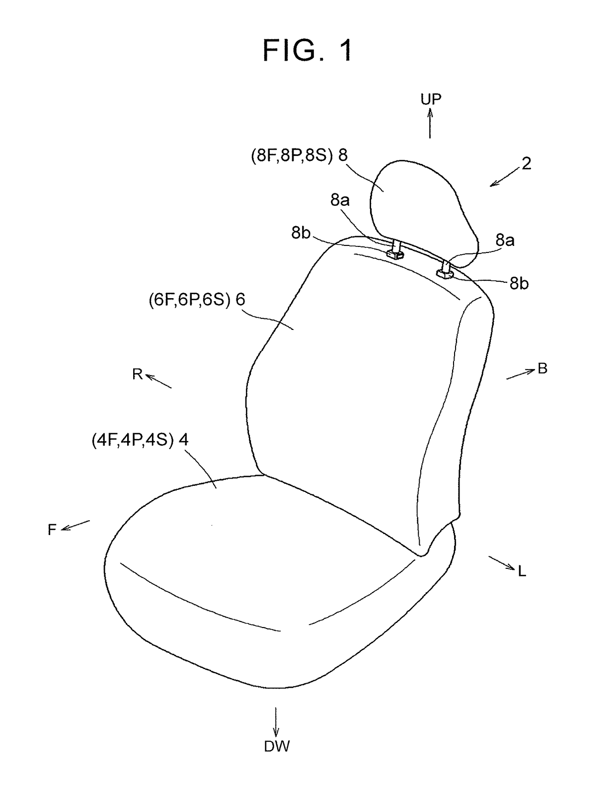
[0023]The following describes an embodiment for carrying out the present invention with reference to FIGS. 1 to 9. In each of the drawings, a reference sign F is assigned to a vehicle-seat forward side, a reference sign B is assigned to a vehicle-seat rearward side, a reference sign UP is assigned to a vehicle-seat upper side, and a reference sign DW is assigned to a vehicle-seat lower side, a reference sign R is assigned to a vehicle-seat right side, and a reference sign L is assigned to a vehicle-seat left side, appropriately. A vehicle seat 2 in FIG. 1 includes a seat cushion 4, a seatback 6, and a headrest 8. These seat components each includes: a seat frame (4F, 6F, 8F) forming a seat framework; a seat pad (4P, 6P, 8P) forming a seat outer shape; and a seat cover (4S, 6S, 8S) covering the seat pad.

[0024]In the present embodiment, a lower part of the seatback 6 is connected to a rear part of the seat cushion 4 in a rising and tilting manner, and the headrest 8 is disposed on an ...


PUM


Abstract

A vehicle seat includes a seat frame. The seat frame has a hollow deformable portion that is bent, and linear recessed portions formed by partially recessing an inner side of the deformable portion. The deformable portion has a linear separation portion formed in a projecting manner relative to the recessed portions and extending on the inner side of the deformable portion. A plurality of recessed portions is formed on each of one side and the other side of the separation portion so as to sandwich the separation portion, and placed independently from each other such that adjacent recessed portions are not connected to each other.

Description

INCORPORATION BY REFERENCE[0001]The disclosure of Japanese Patent Application No. 2015-043925 filed on Mar. 5, 2015 including the specification, drawings and abstract is incorporated herein by reference in its entirety.BACKGROUND OF THE INVENTION[0002]1. Field of the Invention[0003]The present invention relates to a vehicle seat including a metal seat frame (in a hollow tubular shape) that forms a sheet outer shape.[0004]2. Description of Related Art[0005]As such a type of a vehicle seat, there has been known a vehicle seat including a seat cushion and a seatback (see Japanese Utility Model Application Publication No. 5-68353 (JP 5-68353 U)). The seatback is a member connected to the seat cushion in an uprising manner, and includes a metal seat frame (an arch-shaped frame body) that forms a seat framework. The seat frame is a hollow member (a generally rectangular shape in a sectional view), and is formed such that a metal member in a planar shape is molded into a hollow tubular sha...

Claims


Application Information

Patent Timeline
Patent Type & Authority Patents(United States)
IPC IPC(8): B60N2/68A47C5/04B60N2/64
CPCB60N2/68B60N2/643B60N2/64A47C5/043
Inventor TSUJI, HIROSHIAKAIKE, FUMITOSHI
Owner TOYOTA BOSHOKU KK
Why Eureka
Try Eureka