
Cryomill system

Active Publication Date: 2018-04-17
MELNYK CHRISTOPERH T +2
View PDF17 Cites 16 Cited by
  • Summary
  • Abstract
  • Description
  • Claims
  • Application Information

AI Technical Summary

Benefits of technology

The present invention is about a new and improved cryomill system that has various technical benefits and advantages. It can efficiently and safely cryomill powders and other flammable and combustible materials on an industrial scale, using a low cost of manufacture and sale. The system also has a durable and reliable construction, and a can be economically available to the public. The technical effects of this invention include improved efficiency, safety, and economics of cryomill systems.

Problems solved by technology

In that such cryogenic milling of metallic nano-materials is primarily done as research, the methods and components used are inefficient and costly.
Moreover, cryogenic milling avoids flammable substances, such as aluminum and titanium, because the system now used incur the risk of combustion and explosion in the surrounding areas.
While the prior art devices fulfill their respective, particular objectives and requirements, the prior art does not describe cryomill system that allows a safe and efficient method of cryomilling flammable materials on an industrial scale.

Method used


Image

  • Cryomill system
  • Cryomill system
  • Cryomill system

Examples


Embodiment Construction

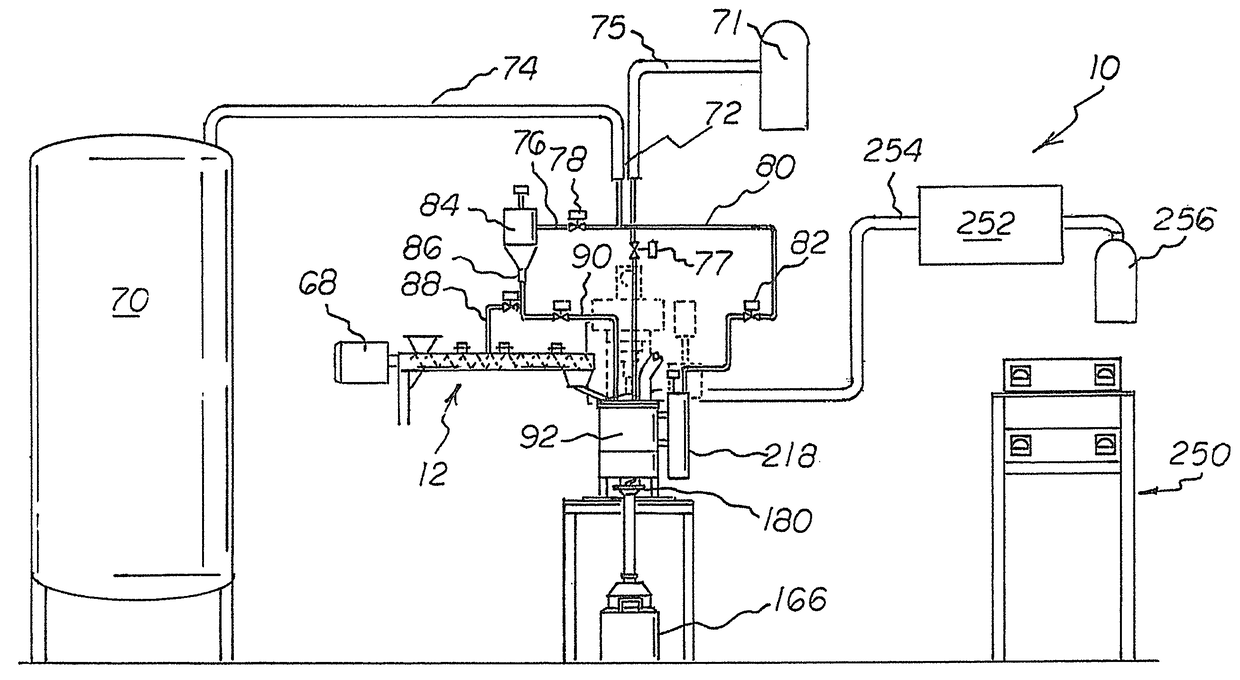
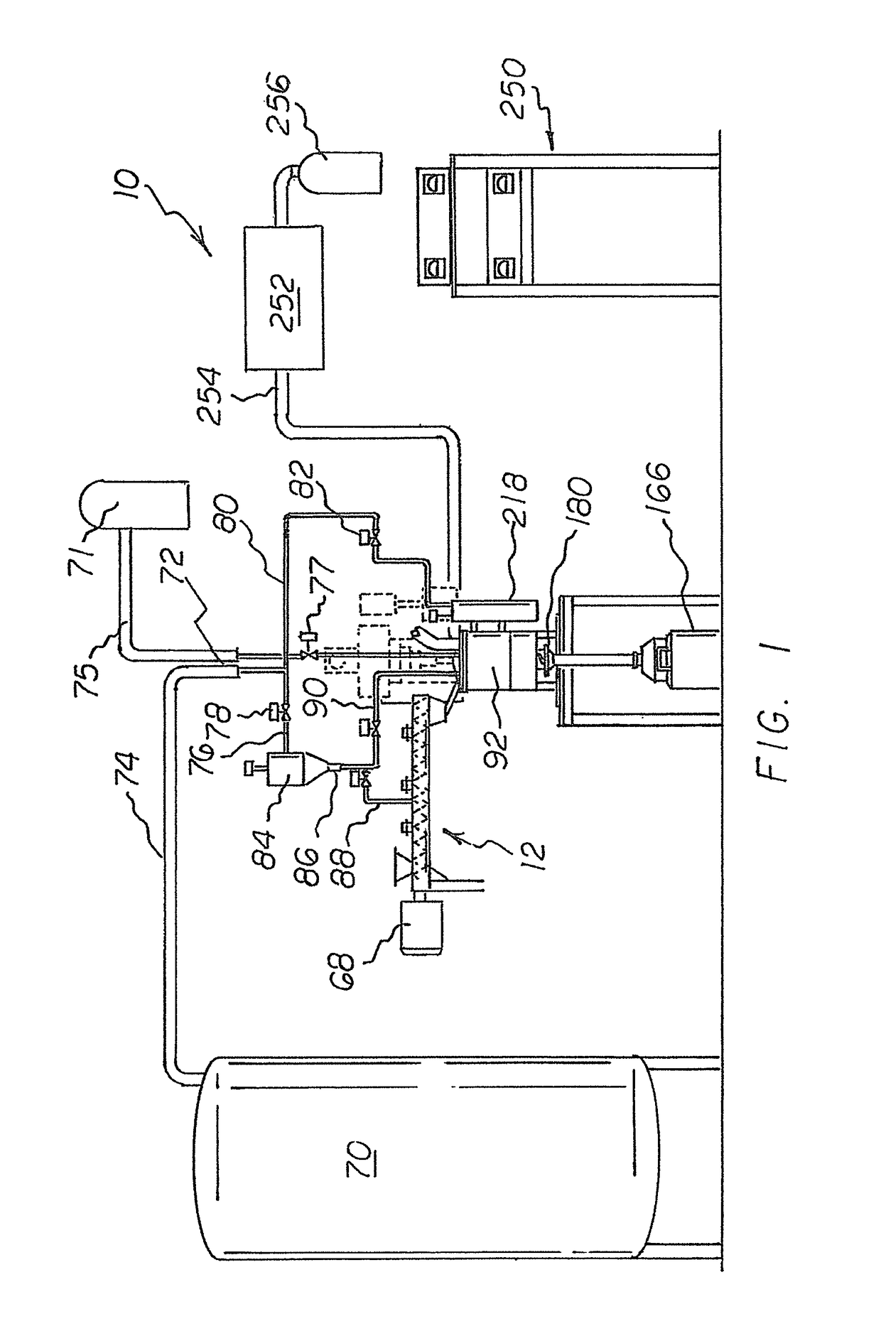
[0058]With reference now to the drawings, and in particular to FIG. 1 thereof, the preferred embodiment of the new and improved cryomill system, embodying the principles and concepts of the present invention and generally designated by the reference numeral 10, will be herein described.

[0059]The present invention, the cryomill system 10 is comprised of a plurality of components. Such components in their broadest context include a coolant source, an intake component, a cryomill, an in-situ condenser system, a collection canister with a gas shielded valve and coolant scavenging system with liquid cryogen return. Such components are individually configured and correlated with respect to each other so as to attain the desired objective.

[0060]A cryomill system 10 comprising several components, in combination, is herein described.

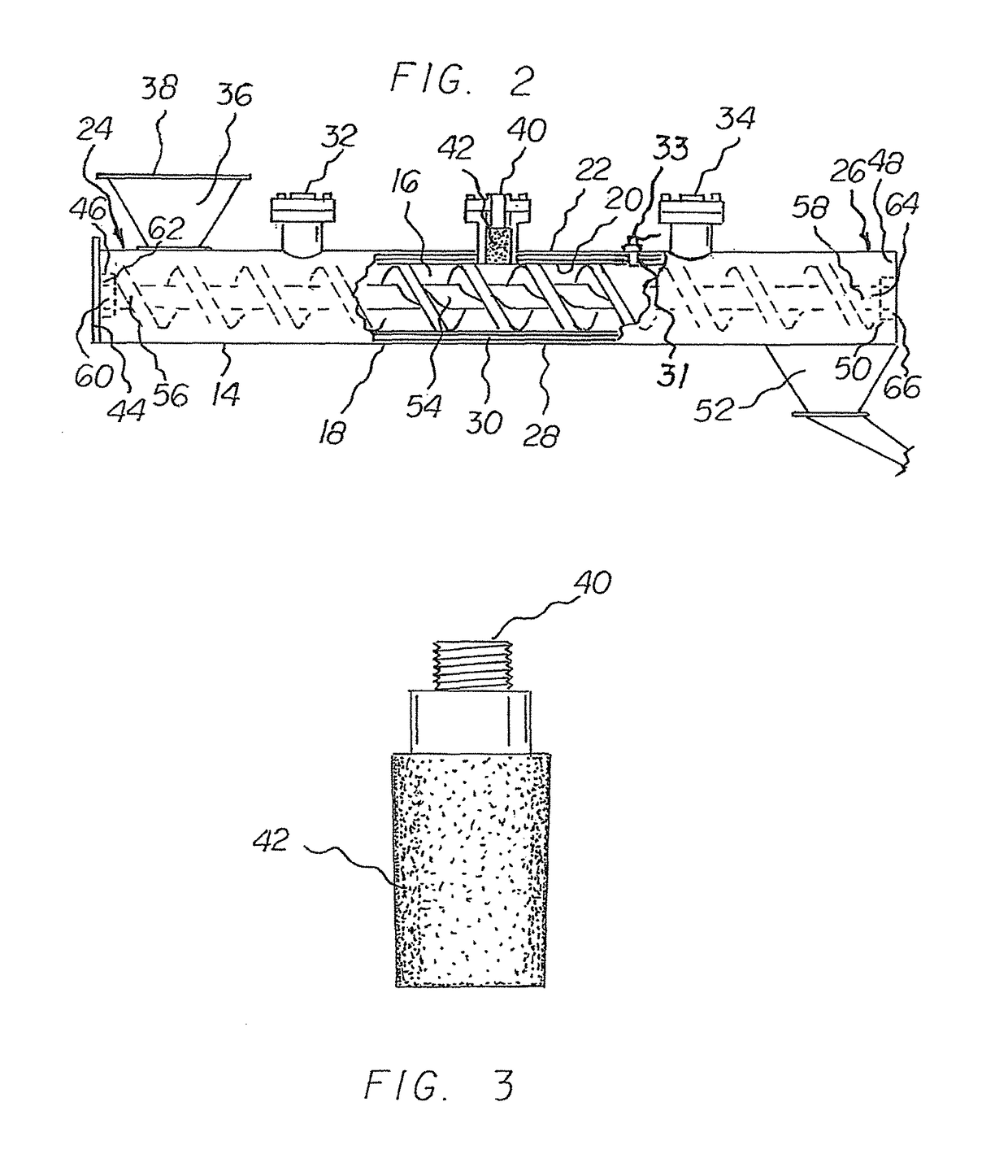
[0061]There is an intake component 12. The intake component comprises a round hollow tube configuration 14 having an interior passageway 16 and a wall 18. The tu...


PUM


Abstract

A cryomill system having an intake component housing an auger, a cooling source containing a liquid coolant being coupled to the cryomill system, a cryomill containment portion, having a mixer located therein and an associated cryomill lid coupled thereto, as well as a collection canister having a poppet valve aperture there through and a gas shielded poppet valve coupling the collection canister to the containment portion.

Description

BACKGROUND OF THE INVENTIONRule 1.78(F) (1) Disclosure[0001]The Applicant has not submitted a related pending or patented non-provisional application within two months of the filing date of this present application. All inventor's names have been disclosed. This application is not under assignment to any other person or entity at this time.FIELD OF THE INVENTION[0002]The present invention relates to a cryomill system and more particularly pertains to a system for the safe and efficient method of cryomilling flammable materials on an industrial scale.DESCRIPTION OF THE PRIOR ART[0003]The use of a device to cryomill substances is known in the prior art. More specifically, devices used to cryomill substances, previously devised and utilized for the purpose of reducing materials to a nanocrystalline structure, are known to consist basically of familiar, expected, and obvious structural configurations, notwithstanding the designs encompassed by the prior art which has been developed for ...

Claims


Application Information

Patent Timeline
IPC IPC(8): B02C17/00B02C17/18F25D3/11
CPCB02C17/1815F25D3/11B02C17/183B02C19/186
Inventor MELNYK, CHRISTOPERH T.WEINSTEIN, BRIAN K.GANSERT, ROBERT V.
Owner MELNYK CHRISTOPERH T
Learn More