Saw system for miter joints

a technology for miter joints and saws, applied in metal sawing accessories, metal sawing apparatuses, manufacturing tools, etc., can solve the problems of linear gauge systems with various levels of complexity, stop-based systems,

Active Publication Date: 2018-04-17
PRECISION AUTOMATION
View PDF174 Cites 3 Cited by
  • Summary
  • Abstract
  • Description
  • Claims
  • Application Information

AI Technical Summary

Benefits of technology

[0005]Many craftsmen, such as framers, finish carpenters, cabinet installers, and cabinetmakers, could benefit from the use of a gauge system to cut pieces with beveled ends for creating miter joints. However, to make the gauge system more attractive to these craftsmen, the system could be improved, for example, to be easier to learn, more accurate at various saw angles, and / or and less likely to induce cutting errors by the user.SUMMARY

Problems solved by technology

Stop-based, linear gauge systems can have various levels of complexity.

Method used


Image

  • Saw system for miter joints
  • Saw system for miter joints
  • Saw system for miter joints

Examples


Embodiment Construction

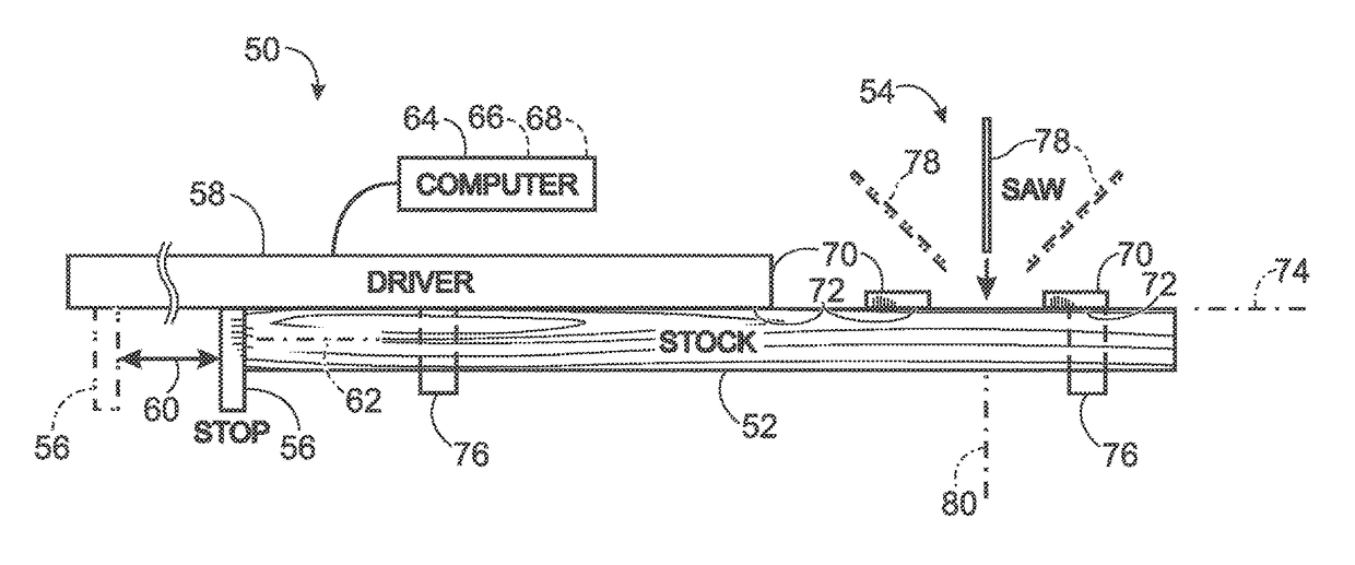
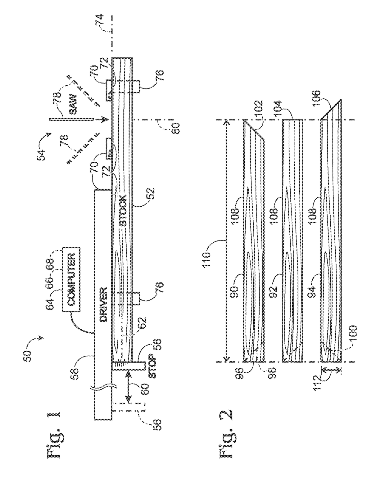
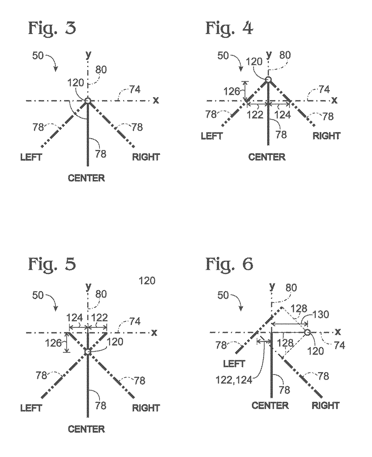
[0037]The present disclosure provides a saw system, including methods and apparatus, for cutting pieces of stock to be installed end-to-end to form miter joints. In some embodiments, the saw system may include a computer that determines an appropriate saw pivot angle for cutting a proximal end of a second piece of stock, based on a corner angle entered for cutting a distal end of a first piece of stock. In some embodiments, the saw system may compensate for an offset pivot axis of a saw based on entered lengths of cut first and second pieces generated respectively with the saw pivoted to the left and to the right.

[0038]An exemplary method of cutting and installing pieces of stock around a wall structure is provided. In the method, a saw system may be provided. The saw system may include a saw device capable of pivoting to cut pieces of stock at various selectable angles relative to a positioning path. The saw system also may include a stop, a driver capable of moving the stop along ...


PUM

PropertyMeasurementUnit
angleaaaaaaaaaa
interior angleaaaaaaaaaa
angleaaaaaaaaaa

Abstract

Saw system, including methods and apparatus, for cutting pieces of stock to be installed end-to-end to form miter joints. In some embodiments, the saw system may include a computer that determines an appropriate saw pivot angle for cutting a proximal end of a second piece of stock, based on a corner angle entered for cutting a distal end of a first piece of stock. In some embodiments, the saw system may compensate for an offset pivot axis of a saw device based on entered lengths of cut first and second pieces generated respectively with the saw device pivoted to the left and to the right.

Description

CROSS-REFERENCE TO PRIORITY APPLICATION[0001]This application is based upon and claims the benefit under 35 U.S.C. § 119(e) of U.S. Provisional Patent Application Ser. No. 61 / 593,754, filed Feb. 1, 2012, which is incorporated herein by reference in its entirety for all purposes.CROSS-REFERENCE TO OTHER APPLICATION[0002]This application incorporates by reference in its entirety for all purposes U.S. Patent Application Publication No. 2011 / 0056344 A1, published Mar. 10, 2011.INTRODUCTION[0003]Computer-controlled positioning systems, also termed gauge systems, are commonly used in manufacturing environments to position workpieces, such as pieces of lumber, pipes, conduits, sheet metal, extrusions, or the like, quickly and accurately relative to a processing tool, such as a saw. In stop-based gauge systems, a stop serves as a movable fence that contacts an end (or other surface) of a workpiece to set the distance from the end to the processing tool. The stop can be driven along a linear...

Claims


Application Information

Patent Timeline
Patent Type & Authority Patents(United States)
IPC IPC(8): B26D3/02B27B27/10B23D59/00
CPCB26D3/02B23D59/008B27B27/10Y10T83/05Y10T29/49826Y10T29/5176
Inventor DICK, SPENCER B.MCCLURE, BRENNAN J.TRAN, MINH DAT BA
Owner PRECISION AUTOMATION
Why Eureka
Try Eureka