Fin plug for a water craft

a technology for fin plugs and watercraft, which is applied in the field of fin plugs, can solve the problems of affecting the installation process, and affecting the installation process, and surrounded by the relatively low density foam of which the surfcraft is formed, so as to achieve the effect of reducing the installation process

Active Publication Date: 2018-05-01
FIN CONTROL SYST
View PDF343 Cites 7 Cited by
  • Summary
  • Abstract
  • Description
  • Claims
  • Application Information

AI Technical Summary

Benefits of technology

[0028]It is further preferred that the base portion of said fin plug includes a plurality of rib elements on an external surface thereof. The main purpose of these rib elements is to enhance the strength and / or structural integrity of the fin plug. The rib elements may also enhance the bonding of the fin plug to a surrounding foam body. This base portion preferably includes a wall section and a floor section which are of substantially uniform thickness. A benefit of this uniform thickness is that it reduces the risk of any deformation of these sections of the fin plug during the cooling of the fin plug (following an injection moulding manufacturing process).
[0041]In a particularly preferred embodiment of this aspect of the invention, an upper end of each in-fill (or at least most of the in-fills) is substantially flush with said top surface. A benefit of this feature is that it results in enhanced bonding between the fin plug assembly and a superimposed layer of fiberglass and resinous material (during the process of installing the fin plug assembly in a water craft, such as a surfboard).
[0045]block up each fin cavity of the fin plug to inhibit fluid material entering into said cavity;
[0051]In an alternative embodiment of the above method the mould chamber has a shape adapted to form a sidewall of the fin plug assembly which has a profile which is substantially identical to the external perimeter of the flange of the planar portion. This can avoid the need to cut away excess foam from the fin plug plus foam block around the sidewall thereof.

Problems solved by technology

As most surfcraft are designed to accommodate three fins, having to adopt this two-step process for forming each fin plug cavity in the surfcraft substantially slows down the installation process.
Another problem with known fin plugs is that the bond formed between the fin plug and the resinous material with which the fin plug is typically secured within a surfboard blank can be, or can become, flawed, particularly as a result of pressure placed upon the surfcraft fin (which, in use, is connected to the fin plug).
A further problem with most known fin plugs (such as those disclosed in U.S. Pat. No. 5,464,359) is that, when installed in a surfcraft, they are surrounded by the relatively low density foam of which the surfcraft is formed.
Such foam may not generally provide sufficient strength to support the loads placed upon the fin plug, due to forces applied to the attached fin, without some deformation, weakening or crushing of the surrounding foam over time.
Such deformation or weakening of the foam may cause the fin plug to sink into the foam or to shift out of alignment, with consequential reduction in performance of the attached fin.
This can also cause the fiberglass skin, in the vicinity of the fin plug, to crack or shatter.
Also, when the fin plug sinks into the foam body, it can cause the top surface of the fin plug to separate from the adjoining fiberglass layer.
In turn, these connections can be weakened and, in some cases, the hardened resinous material can crack).

Method used


Image

  • Fin plug for a water craft
  • Fin plug for a water craft
  • Fin plug for a water craft

Examples


second example manufacturing

Technique of the Composite Foam and Fin Plug Assembly.

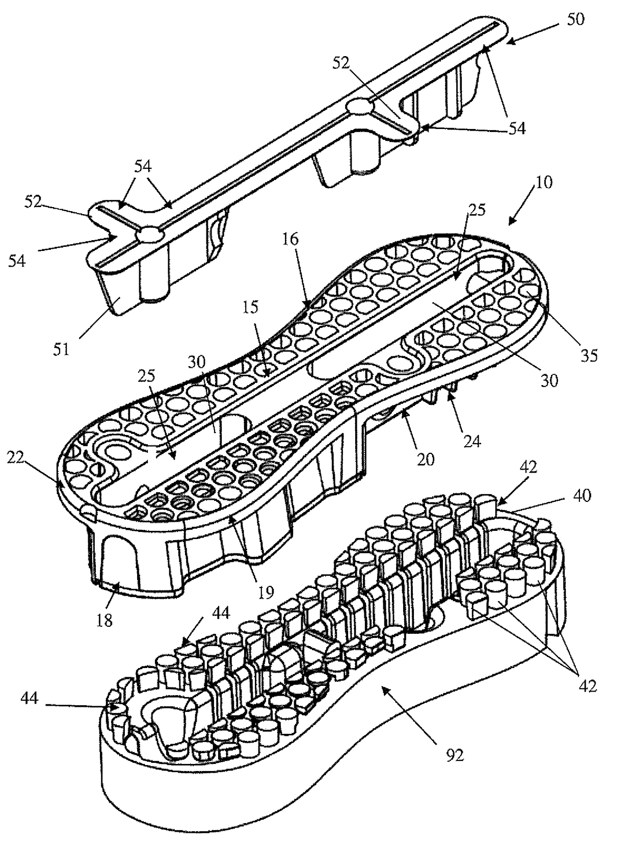
[0206]An alternative to the first example manufacturing technique is to sacrifice the first cavity insert at step 6) when excess foam is being removed. In situations where the foam has covered the top surface 15 and the cavity insert 50, it may be more economic and time efficient to use a router or other tool to remove the foam above the cavity insert without precautions to maintain the integrity of the cavity insert. A new cavity insert may be used to replace the cavity insert used in foam moulding. The new cavity insert would also have the cross hair markers 54 for guiding the positioning of the second template guide when using a router to obtain access to the fin cavities through the glass layer 60.

[0207]The use of a sacrificial cavity insert may then be used for the forming of the composite foam and fin plug assembly of the first example for the example Figures referenced. It may be particularly useful where the excess of foa...


PUM


Abstract

A fin plug (10) for a water craft, said fin plug (10) including: a top surface (15) and a bottom surface (20); at least one fin cavity (25), for receiving a base element of a fin, extending inwardly from at least one opening in the top surface (15); and at least one hole (35) or recess in the top surface (15) adapted to be filled with foam.

Description

FIELD OF THE INVENTION[0001]The present invention relates to a fin plug, for installation in a water craft, such as a surfboard or the like, adapted to enable a fin to be removably attached to the water craft.BACKGROUND OF THE INVENTION[0002]A water craft, such as a surf-craft, particularly one on which a person stands, kneels or sits, when traversing water or riding a wave, generally has at least one fin in an underside of the craft, generally near the tail end of the craft. Such fins have a number of functions, including: enabling the craft to travel in a desired direction; facilitating the turning of the craft; preventing the craft from slipping sideways; and providing greater control over the movement of the craft, such as when riding a wave.[0003]The following discussion is directed mainly to surf-craft, such as surfboards, but it is to be understood that the discussion applies equally to other water craft (and surf craft) which are adapted to include fins, such as sail boards,...

Claims


Application Information

Patent Timeline
Patent Type & Authority Patents(United States)
IPC IPC(8): B63B1/00B63B35/79B63B35/00
CPCB63B35/793B63B32/66
Inventor SCOTT, GREGORYDURANTE, MICHAEL
Owner FIN CONTROL SYST
Why Eureka
Try Eureka