Damper disk assembly

a technology of adamper disc and a spherical disc, which is applied in the direction of mechanical actuators, mechanical apparatus, couplings, etc., can solve the problems that the torque required in idling mainly performed in the low torsion angular range cannot be obtained depending on the limit on widening so as to achieve widen the low torsion angular rang

Active Publication Date: 2018-05-08
EXEDY CORP
View PDF22 Cites 2 Cited by
  • Summary
  • Abstract
  • Description
  • Claims
  • Application Information

AI Technical Summary

Benefits of technology

[0010]In the damper disc assembly described in Japan Laid-open Patent Application Publication No. H10-339355, the sub damper unit is disposed laterally to the flange so as to widen the low torsion angular range. Therefore, noises in idling can be effectively inhibited.
[0012]It is an object of the present invention to effectively attenuate noises in idling and vibrations by particularly widening the low torsion angular range and to obtain a torque required in idling.Solution to Problems

Problems solved by technology

Hence, the circumferential space for disposing the sub damper unit is small, and this imposes a limitation on widening the low torsion angular range.
Therefore, chances are that a torque required in idling mainly performed in the low torsion angular range cannot be obtained depending on the specifications of vehicles.

Method used


Image

  • Damper disk assembly
  • Damper disk assembly
  • Damper disk assembly

Examples


Embodiment Construction

[0037][Entire Construction]

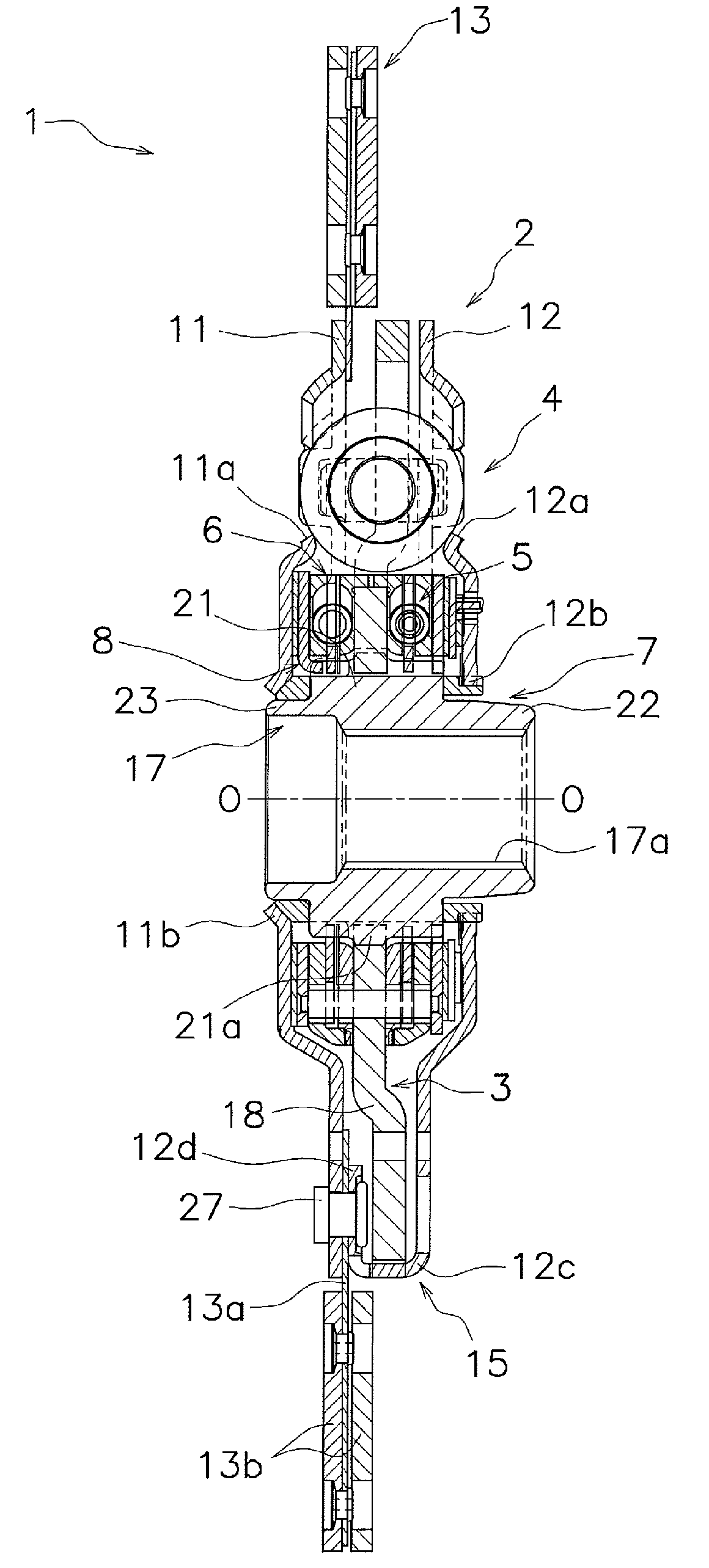
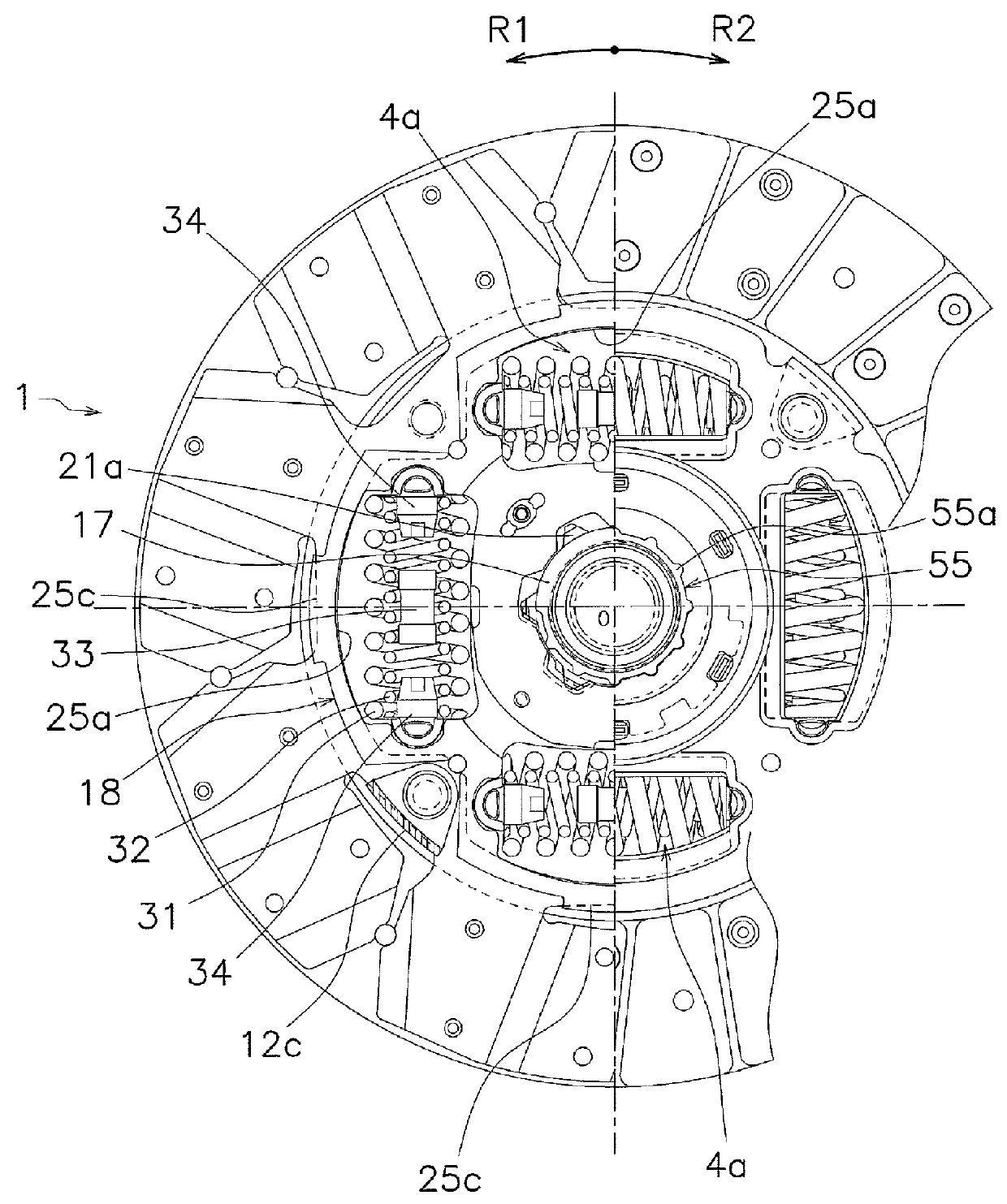
[0038]FIGS. 1 and 2 show a clutch disc assembly 1 including a damper disc assembly according to an exemplary embodiment of the present invention. FIG. 1 is a cross-sectional view of the clutch disc assembly 1, whereas FIG. 2 is a front view of the clutch disc assembly 1. The clutch disc assembly 1 is used as a clutch device for a vehicle, and has a clutch function and a damper function. In FIG. 1, line O-O indicates the rotational axis of the clutch disc assembly 1, i.e., a rotational center line. Additionally, in FIG. 1, an engine and a flywheel (not shown in the drawing) are disposed on the left side whereas a transmission (not shown in the drawing) is disposed on the right side. Moreover, in FIG. 2, an R1 side indicates a rotation-directional drive side (positive side) of the clutch disc assembly 1 whereas an R2 side indicates the opposite side (negative side) to the rotation-directional drive side.

[0039]The clutch disc assembly 1 mainly includes an inp...


PUM


Abstract

A damper disc assembly includes first and second input plates, an output unit, a high stiffness damper unit, and first and second low stiffness damper units. The output unit includes an input-side member and an output-side member disposed rotatably relative to each other. The high stiffness damper unit elastically couples the input-side member and the first and second input plates in a rotational direction and is actuated in a high torsion angular range of torsional characteristics. The first and second low stiffness damper units elastically couple the input-side member and the output-side member and are actuated in a low torsion angular range of the torsional characteristics. The second low stiffness damper unit is actuated later than actuation of the first low stiffness damper unit.

Description

CROSS-REFERENCE TO RELATED APPLICATIONS[0001]This application is the U.S. National Phase of PCT International Application No. PCT / JP2014 / 072782, filed on Aug. 29, 2014. That application claims priority to Japanese Patent Application No. 2013-182562, filed Sep. 3, 2013. The contents of both applications are herein incorporated by reference in their entirety.BACKGROUND[0002]Technical Field[0003]The present invention relates to a damper disc assembly, particularly to a damper disc assembly configured to attenuate variation in torque inputted thereto from an engine and transmit the torque toward a transmission.[0004]Background Art[0005]In general, noises and vibrations of vehicles include noises in idling, noises in traveling and tip-in / tip-out (low frequency vibrations). Damper disc assemblies are provided for inhibiting the aforementioned noises and vibrations.[0006]In torsional characteristics of a damper disc assembly, a low torsion angular range relates to noises in idling, and a l...

Claims


Application Information

Patent Timeline
Patent Type & Authority Patents(United States)
IPC IPC(8): F16D3/12F16F15/134F16D13/64
CPCF16D3/12F16F15/134F16D13/64F16D2300/22F16F15/12333F16F15/12346F16F15/1238
Inventor KUBOTA, YOSHITAKAHASHIMOTO, KAZUKIMATSUMURA, RYOTA
Owner EXEDY CORP
Why Eureka
Try Eureka