Preventing shorting between source and/or drain contacts and gate

a technology of drain contacts and source contacts, applied in the field of semiconductor structure fabrication, can solve the problems of insufficient spacer-to-spacer distance for contact formation, electrical shorting between drain contacts and source and drain contacts, etc., and achieve the effect of preventing electrical shorts

Inactive Publication Date: 2018-05-15
GLOBALFOUNDRIES U S INC
View PDF5 Cites 0 Cited by
  • Summary
  • Abstract
  • Description
  • Claims
  • Application Information

AI Technical Summary

Benefits of technology

[0003]Thus, a need continues to exist for preventing electrical shorts between conductive gates and source and drain contacts of FinFET-based semiconductor devices.
[0005]In accordance with another aspect, a method of forming at least one FinFET is provided. The method includes forming a gate structure, the gate structure surrounding a channel of the at least one FinFET, the gate structure including a conductive gate electrode, spacers adjacent to sidewalls of the metal gate electrode, and a thick gate cap having a thickness of between about 30 nm and about 50 nm. The method further includes forming a source and a drain, the channel being situated between the source and the drain, forming two-part conductive contacts for the source and the drain, each of the conductive contacts having a bottom part adjacent the thick gate cap and a top part above and in at least partial contact with the bottom part. A combination of the thick gate cap and the two-part source and drain contacts prevent electrical shorts between the conductive gate electrode and the source and the drain.

Problems solved by technology

However, such self-aligned contacts suffer from insufficient spacer-to-spacer distance for contact formation.
In addition, variations in the resulting gate cap size leads to electrical shorting between the conductive gate and source and drain contacts.

Method used


Image

  • Preventing shorting between source and/or drain contacts and gate
  • Preventing shorting between source and/or drain contacts and gate
  • Preventing shorting between source and/or drain contacts and gate

Examples


Embodiment Construction

[0017]Aspects of the present invention and certain features, advantages, and details thereof, are explained more fully below with reference to the non-limiting examples illustrated in the accompanying drawings. Descriptions of well-known materials, fabrication tools, processing techniques, etc., are omitted so as not to unnecessarily obscure the invention in detail. It should be understood, however, that the detailed description and the specific examples, while indicating aspects of the invention, are given by way of illustration only, and are not by way of limitation. Various substitutions, modifications, additions, and / or arrangements, within the spirit and / or scope of the underlying inventive concepts will be apparent to those skilled in the art from this disclosure.

[0018]Approximating language, as used herein throughout the specification and claims, may be applied to modify any quantitative representation that could permissibly vary without resulting in a change in the basic fun...


PUM


Abstract

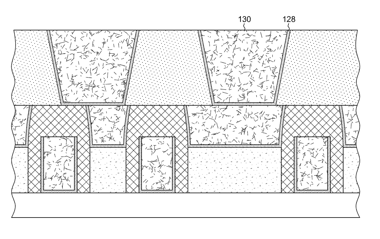
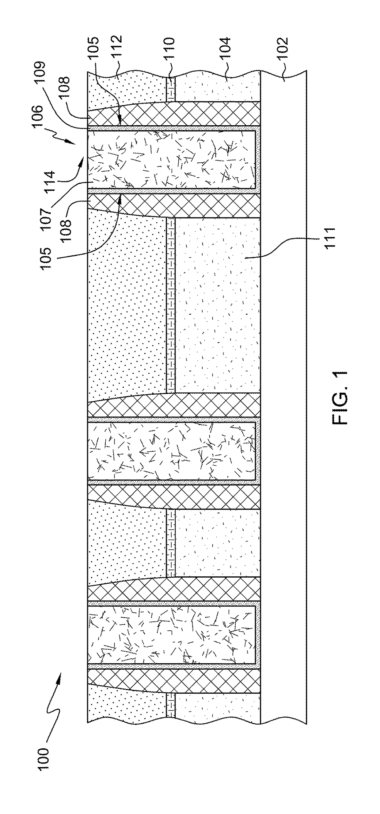
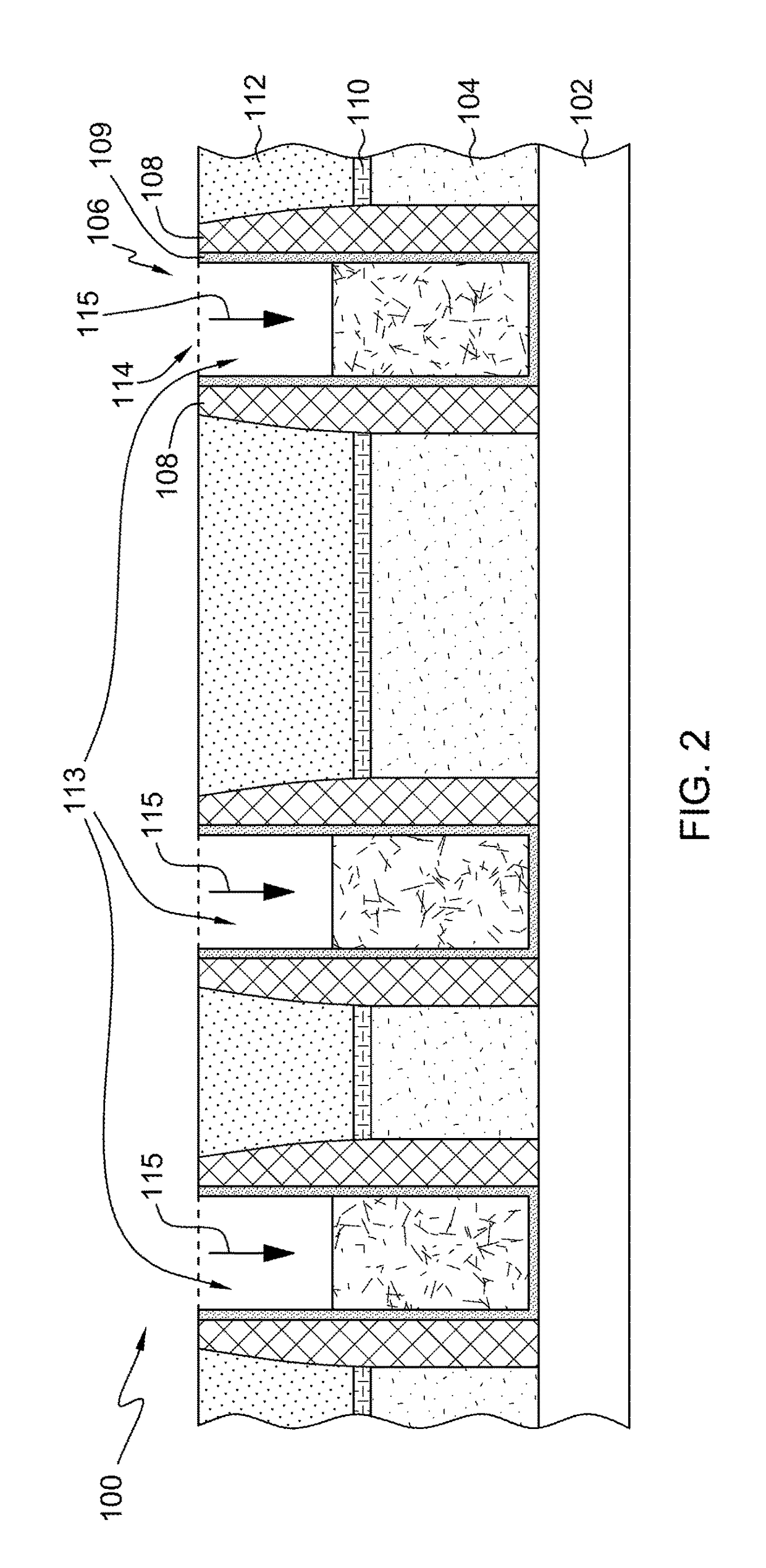
Electrical shorting between source and / or drain contacts and a conductive gate of a FinFET-based semiconductor structure are prevented by forming the source and drain contacts in two parts, a bottom contact part extending up to a height of the gate cap and an upper contact part situated on at least part of the bottom contact part.

Description

BACKGROUNDTechnical Field[0001]The present invention generally relates to fabrication of semiconductor structures. More particularly, the present invention relates to preventing electrical shorting between source and / or drain contacts and their associated gate in a FinFET-based semiconductor device.Background Information[0002]In modern FinFET-based semiconductor fabrication, self-aligned contacts have been used to accommodate the ever-shrinking size of such devices. However, such self-aligned contacts suffer from insufficient spacer-to-spacer distance for contact formation. In addition, variations in the resulting gate cap size leads to electrical shorting between the conductive gate and source and drain contacts.SUMMARY[0003]Thus, a need continues to exist for preventing electrical shorts between conductive gates and source and drain contacts of FinFET-based semiconductor devices.[0004]The shortcomings of the prior art are overcome and additional advantages are provided through the...

Claims


Application Information

Patent Timeline
Patent Type & Authority Patents(United States)
IPC IPC(8): H01L21/28H01L29/417H01L21/8234H01L21/3105H01L27/088
CPCH01L27/0886H01L21/31053H01L29/41791H01L21/823437H01L21/823475H01L21/823431H01L29/66795H01L29/785
Inventor SURISETTY, CHARAN V.SCHEPIS, DOMINIC J.CHENG, KANGGUOREZNICEK, ALEXANDER
Owner GLOBALFOUNDRIES U S INC
Why Eureka
Try Eureka