Reverse type stamp

a reverse type and stamp technology, applied in stamping and printing, etc., can solve the problems of imprint blur, ink pad sagged, quality deterioration such as imprint spots, etc., to prevent the transfer load from being unnecessarily increased, prevent the spot and seal imprint blur, and prevent the effect of ink pad sagged

Active Publication Date: 2018-05-22
SHACHIHATA IND
View PDF7 Cites 0 Cited by
  • Summary
  • Abstract
  • Description
  • Claims
  • Application Information

AI Technical Summary

Benefits of technology

[0006]An advantage of some aspects of the invention is to provide a reverse type stamp capable of preventing an ink pad from being sagged due to a contact with a stamp surface and a transfer load from being unnecessarily increased in accordance with a dimensional change of a molded article or the like while ensuring the air-tightness of the ink pad even when a variation in dimension occurs in a molded article (a stamp surface) or a print body.
[0015]According to the reverse type stamp of the invention, since the movable container is elastically supported, a contact between the ink pad and the stamp surface is buffered. Thus, it is possible to prevent the ink pad from being sagged and to prevent the transfer load from being unnecessarily increased in accordance with the dimensional change of the molded article (the stamp surface). Accordingly, it is possible to prevent the spot and the blur of the seal imprint.
[0016]Further, according to the reverse type stamp of the invention, the inside of the ink cartridge is sealed through the sealing member provided at the inversion body used for joining the print body. In this configuration, since the sealed surface of the ink cartridge receiving the sealing member is formed in a tapered shape, it is possible to realize the air-tightness of the ink cartridge by a force smaller than that of the conventional configuration in which the sealing member is received by the flat surface. Since the air-tightness of the ink pad is sufficiently ensured and a large urging force for improving the sealability of the ink cartridge is not needed, a force (a force against the urging force of the elastic member) for the imprinting operation may be small.

Problems solved by technology

For this reason, when a highly repellent spring is used and a stamp surface having an unevenness contacts the ink pad for a long period of time, the ink pad may be sagged.
As a result, since an unevenness may occur in the ink adhesion amount on the stamp surface, quality deterioration such as imprint spots may occur.
Further, since a transfer load of the stamp surface in accordance with a dimensional change (variation) of a molded article may be unnecessarily increased, quality deterioration such as imprint blur may occur due to an increase in ink adhesion amount of the stamp surface.

Method used


Image

  • Reverse type stamp
  • Reverse type stamp
  • Reverse type stamp

Examples


Embodiment Construction

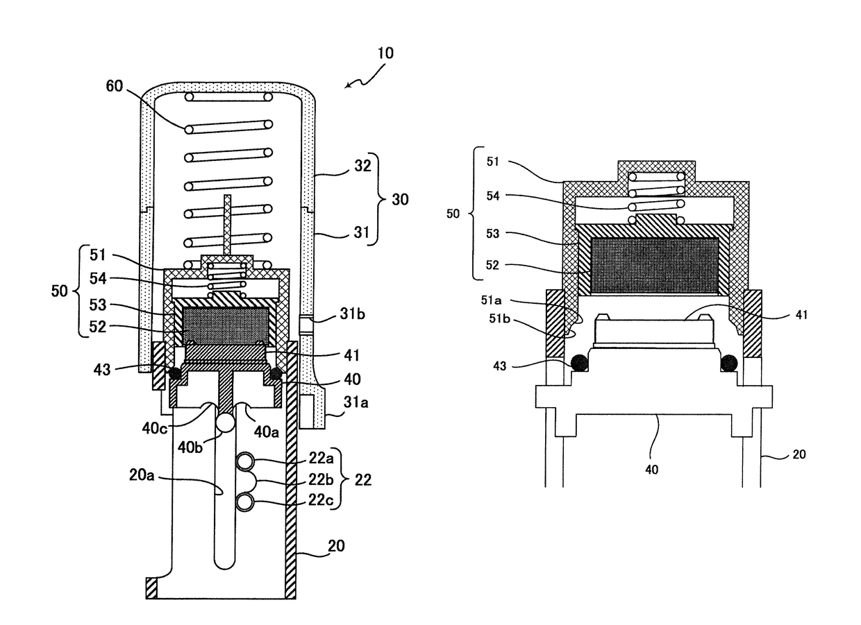
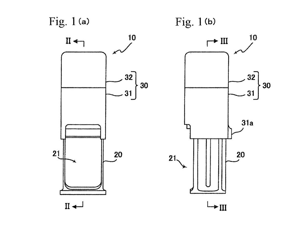
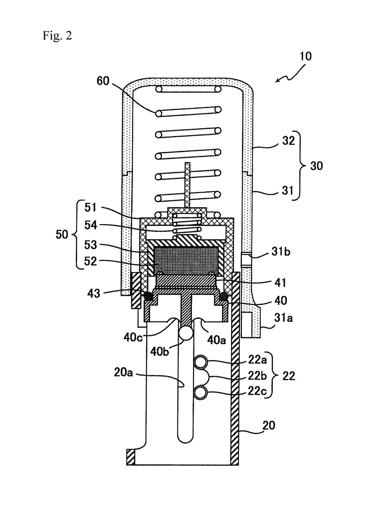
[0024]Hereinafter, a configuration of a reverse type stamp 10 according to a preferred embodiment of the invention will be described with reference to the drawings. FIG. 1(a) is a front view of the reverse type stamp 10 and FIG. 1(b) is a side view of the reverse type stamp 10. FIG. 2 is a cross-sectional view of the reverse type stamp illustrated in FIG. 1(a), taken along a line II-II thereof and FIG. 3 is a cross-sectional view of the reverse type stamp illustrated in FIG. 1(b), taken along a line III-III thereof.

[0025]The reverse type stamp 10 includes an outer cylindrical body 30, an inner cylindrical body 20 which is fitted to the outer cylindrical body 30 to be relatively movable to each other, a coil spring 60 which is a first elastic member constantly urging the inner cylindrical body 20 in a protruding direction inside the outer cylindrical body 30, an inversion body 40 which is configured to be able to be reversed and returned in synchronization with the sliding motion bet...


PUM


Abstract

A reverse type stamp includes an outer cylindrical body, an inner cylindrical body which is movable relative to the outer cylindrical body, an elastic member that constantly urges the inner cylindrical body in a protruding direction inside the outer cylindrical body, an inversion body which is reversed and returned in synchronization with the relative movement, and a print body which is joined to the inversion body. When the outer cylindrical body is pressed down while the inner cylindrical body stands on a paper surface, the inversion body is reversed inside the inner cylindrical body for an imprinting operation. An ink pad is provided inside a movable container inside a cartridge. The movable container is elastically supported inside the cartridge by a coil spring provided at a rear surface thereof. Since contact between the ink pad and the print body is buffered, the sagging of the ink pad can be prevented.

Description

BACKGROUND OF THE INVENTION[0001]1. Field of the Invention[0002]The present invention relates to a reverse type stamp which performs an imprinting operation by reversing a print body.[0003]2. Description of the Related Art[0004]Conventionally, a reverse type stamp is known in which an ink pad is brought into contact with a stamp surface of a print body to supply ink thereto and the stamp surface is reversed downward while a grip is pressed to perform an imprinting operation (for example, see JP 2011-25659 A). Particularly when quick-drying ink is used in this kind of stamp, it is necessary to enhance the air-tightness of the ink pad in order to prevent volatilization and drying of the ink. For example, JP 49-37727 A discloses a technology of preventing ink from being quickly dried by pressing a side wall of a print body against the periphery of an ink pad when a stamp is not used.[0005]When quick-drying ink is used, it is necessary to ensure the air-tightness of the ink pad even whe...

Claims


Application Information

Patent Timeline
Patent Type & Authority Patents(United States)
IPC IPC(8): B41K1/02B41K1/40B41K1/22B41K1/04B41K3/56
CPCB41K1/22B41K1/02B41K1/40B41K1/04B41K3/56B41K1/36B41K1/38B41K1/58
Inventor KOIDE, TAKUYA
Owner SHACHIHATA IND
Why Eureka
Try Eureka