Method of manufacturing wire harness

a manufacturing method and wire harness technology, applied in the direction of electrical equipment, line/current collector details, coupling device connections, etc., can solve the problem of design restrictions

Inactive Publication Date: 2012-12-27
HITACHI METALS LTD
View PDF14 Cites 2 Cited by
  • Summary
  • Abstract
  • Description
  • Claims
  • Application Information

AI Technical Summary

Benefits of technology

[0011]In this wire harness, the melting member is inserted into a cable insertion hole through an insertion portion formed on the housing and is pressed against a pressure receiving portion formed on an inner surface of the cable insertion hole while vibrating the melting member by an ultrasonic vibration horn to melt a front end portion of the melting member which is in contact with the pressure receiving portion, and the molten resin is poured into a gap between the cables and the cable insertion holes so that peripheries of the cables are covered with the molten resin, thereby ensuring air-tightness of the housing.
[0016]solidifying the molten resin inside the space to resin-seal the gap between the insertion hole and the plurality of wires,
[0028]According to one embodiment of the invention, a method of manufacturing a wire harness is conducted such that the resin member is melted outside the airtight block and the molten resin is supplied into the gap through the flow channel. Thus, the airtight block does not directly receive the ultrasonic vibration or heat generated by the ultrasonic vibration unlike in the case of melting the resin member inside the airtight block by applying the ultrasonic vibration thereto. Therefore, the airtight block can be prevented from being deformed by the heating.

Problems solved by technology

However, in the waterproof structure of a connector described in JP-A-2000-353566, a material which can be melted and adhered to the resin of the connector needs to be selected for the resin coating of the wire, which is restriction in designing.
However, not only the melting member but also the pressure receiving portion of the housing may be melted at the time of pressing and simultaneously vibrating the melting member and it is not possible to supply sufficient molten resin to a gap between the cables and the cable insertion hole in such a case, hence, there is still room for improvement.

Method used


Image

  • Method of manufacturing wire harness
  • Method of manufacturing wire harness
  • Method of manufacturing wire harness

Examples


first embodiment

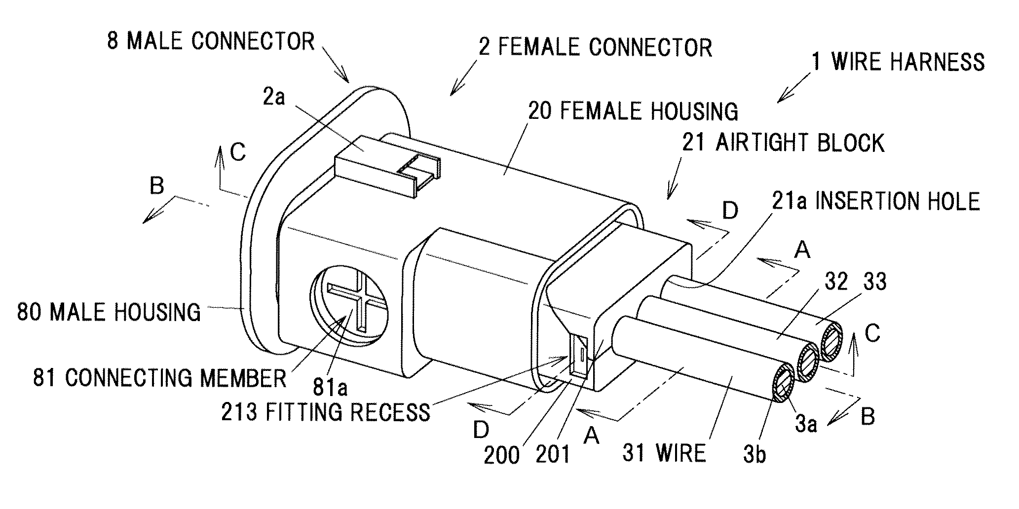
[0048]FIG. 1 is a perspective view showing a wire harness in a first embodiment of the invention FIG. 2 is a cross sectional view taken along a line A-A in FIG. 1. A wire harness 1 is used for supplying a driving current to, e.g., an electric motor as a drive source of a vehicle.

[0049]The wire harness 1 has a female connector 2 and three wires 31 to 33. The female connector 2 has a female housing 20 for holding end portions of the wires 31 to 33. The three wires 31 to 33 are aligned in one direction and are held by the female housing 20. The female housing 20 is formed of a resin, e.g., PPS (polyphenylene sulfide) resin, PPA (polyphthalamide) resin, PA (polyamide) resin or PBT (polybutylene terephthalate) resin, etc.

[0050]The female housing 20 has, at an end portion thereof from which the wires 31 to 33 are led out, an airtight block 21 formed of a resin in which an insertion hole 21a for inserting the wires 31 to 33 is formed. Meanwhile, a fitting recess 213 for fitting a below-des...

second embodiment

[0126]Next, the second embodiment of the invention will be described in reference to FIGS. 16A and 16B.

[0127]FIGS. 16A and 16B are diagrams illustrating a melting tool 5A and a resin member 6A in a second embodiment, wherein FIG. 16A is a plan view and FIG. 16B is a cross sectional view taken along a line H-H in FIG. 16A. An outline of the columnar resin member 6A inserted into the melting tool 5A is indicated by a chain double-dashed line in FIG. 16A, and FIG. 16B shows a cross section along the center axis C of the resin member 6A. The melting tool 5A is attached to the airtight block 21 of the female housing 20 and supplies a molten resin to the space 21b of the airtight block 21 in the same manner as the melting tool 5 in the first embodiment.

[0128]The melting tool 5A is formed of a metal, e.g., iron, stainless steel or aluminum, etc., and integrally includes a main body 53 and a protruding portion 54. The melting tool 5A has an insertion hole 531 for inserting the resin member ...


PUM

PropertyMeasurementUnit
distanceaaaaaaaaaa
temperatureaaaaaaaaaa
angleaaaaaaaaaa

Abstract

A method of manufacturing a wire harness including a plurality of wires and a connector with a housing. The method includes arranging the plurality of wires in an insertion hole of an airtight block of the housing to have a gap between the plurality of wires and an inner surface of the insertion hole, supplying a molten resin having a fluidity into the gap through a flow channel in communication with the gap, and solidifying the molten resin inside the space to resin-seal the gap between the insertion hole and the plurality of wires. The supplying of the molten resin is conducted such that a tool for melting a solid resin member is attached to the airtight block, the resin member is melted by applying an ultrasonic vibration while being pressed against the tool, and the molten resin obtained by the melting is poured into the flow channel.

Description

[0001]The present application is based on Japanese patent application Nos 2011-138338 and 2012-021761 filed on Jun. 22, 2011 and Feb. 3, 2012, respectively; the entire contents of which are incorporated herein by reference.BACKGROUND OF THE INVENTION[0002]1. Field of the Invention[0003]The invention relates to a method of manufacturing a wire harness including plural wires and a connector with a housing for holding end portions of the plural wires.[0004]2. Description of the Related Art[0005]In a conventional wire harness provided with plural wires and a connecter provided at end portions of the plural wires, a gap between a housing of the connector and the wires is air-tightly sealed in order to prevent failure which is caused by moisture, etc., entering inside the connector (see, e.g., JP-A-2001-345143 and JP-A-2000-353566).[0006]In the connector described in JP-A-2001-345143, plural insertion holes for inserting the respective plural wires are formed on the housing and rubber plu...

Claims


Application Information

Patent Timeline
Patent Type & Authority Applications(United States)
IPC IPC(8): H01R43/00
CPCH01R13/5208H01R13/5216Y10T29/49002Y10T29/49117Y10T29/49174
Inventor KATAOKA, YUTATAKEHARA, HIDEAKIFUKUDA, KUNIHIROSUZUKI, SACHIOUMETSU, JUNHAYASHI, SHINYA
Owner HITACHI METALS LTD
Why Eureka
Try Eureka