Wind power generator

a wind power generator and generator technology, applied in the direction of electric generator control, machines/engines, mechanical equipment, etc., can solve the problems of generator exhaustion, damage to the structure, and the inability to use the structure of the wind power generator

Active Publication Date: 2011-12-22
SONAJALG ANDRES +1
View PDF10 Cites 2 Cited by
  • Summary
  • Abstract
  • Description
  • Claims
  • Application Information

AI Technical Summary

Benefits of technology

[0009]to ensure the required air-tightness considering that the wind power generators are mostly positioned in the sea, ocean and on the coast, where in addition to the humidity the wind also carries the particles of mineral salts from the sea water, which in turn cause the premature corrosion of the details, considerable deterioration of the insulation of the generator and electric puncture in the windings.
[0010]For that purpose the authors of the invention suggest such a wind power generator structure where the main shaft of the wind power generator is hollow, i.e. the shaft has a tubular structure. At one end of the tube an impeller head with blades is fixed, and the other end contains a generator with a rotor and stator. The main shaft is supported in the generator body, which is formed of a tube with the help of a bearing or bearings, which have been installed at the centre of the outer surface of the main shaft onto the first part. The bearings can comprise both ball bearings and roller bearings (also inclined roller bearings), for the state-of-the-art technologies enable to make bearing rollers and bearings with any size. At the same time, such structure ensures the air-tightness between the main shaft and the body, simultaneously, the air flows through the main shaft, with the help of which necessary knots and components are cooled.

Problems solved by technology

The kinds of generators present the problem of exhaustion caused by the transmission of main shaft-reducer-generator.
Furthermore, such structure cannot be used for wind power generators that exceed the capacity of 1,500 kW as the torque generated by the main shaft and reducer becomes too excessive, and the construction suffers from exhaustion and material fatigue, which may result in damage to the structure.
The weakness of such a solution lies in the connections of the console and the tower as the wind power acts upon the turbine (blade length 35-40 m) is transferred to the connections of the console, which are thus subject to material fatigue and may break.
Furthermore, these kinds of wind power generators are also problematic due to insufficient cooling; the air-tightness of the windings in the generator structure should me ensured at the same time.
Different solutions have been proposed, but so far the cooling and structural reliability remain problematic.
Also, the proposed solutions are expensive and material consuming.

Method used


Image

  • Wind power generator
  • Wind power generator
  • Wind power generator

Examples


Embodiment Construction

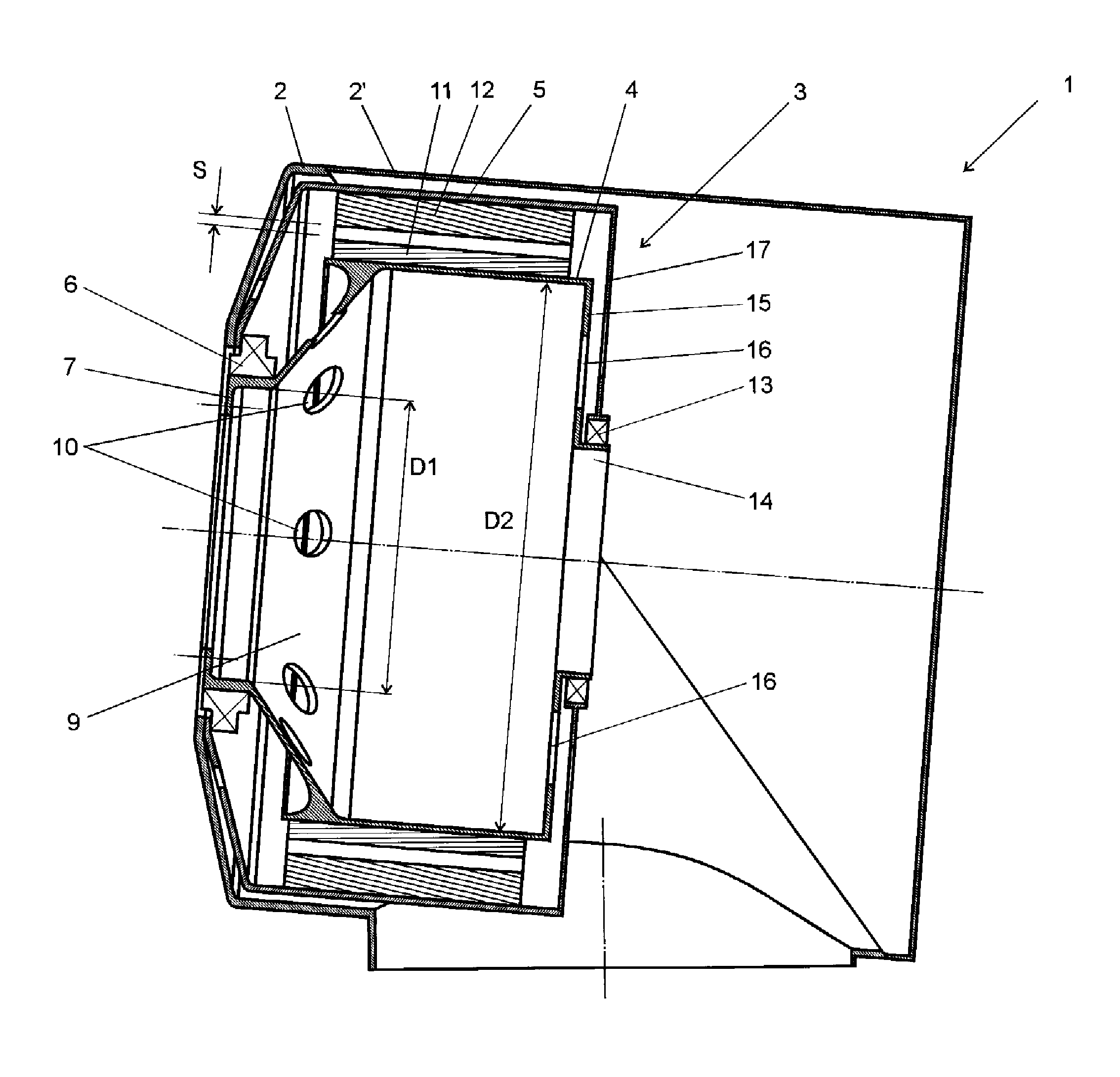
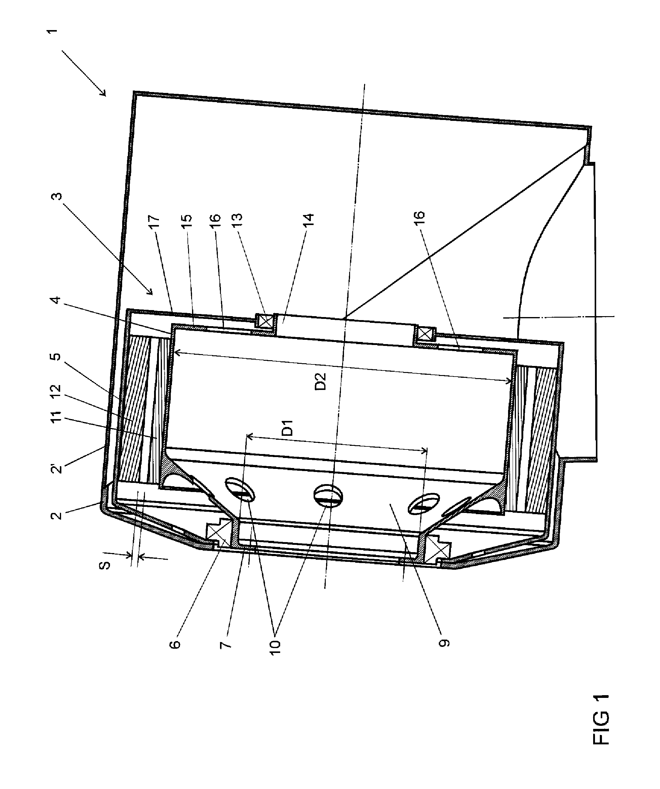
[0015]The wind power generator 1 depicted in the drawings is via the connections known in the field of the art to the top of the bearing tower, etc. of the wind power generator. Wind power generator 1 comprises two-part main body 2, 2′, which surrounds the generator part 3, or working chamber, an impeller head (not shown in the drawings), which holds the blades of the generator and a connection part (not shown) by which the wind power generator 1 is fixed to the tower, which lies on the ground on a special base (not shown). The interior of the tower has the knots and components arranged and installed, which are necessary for the operation of the wind power generator 1.

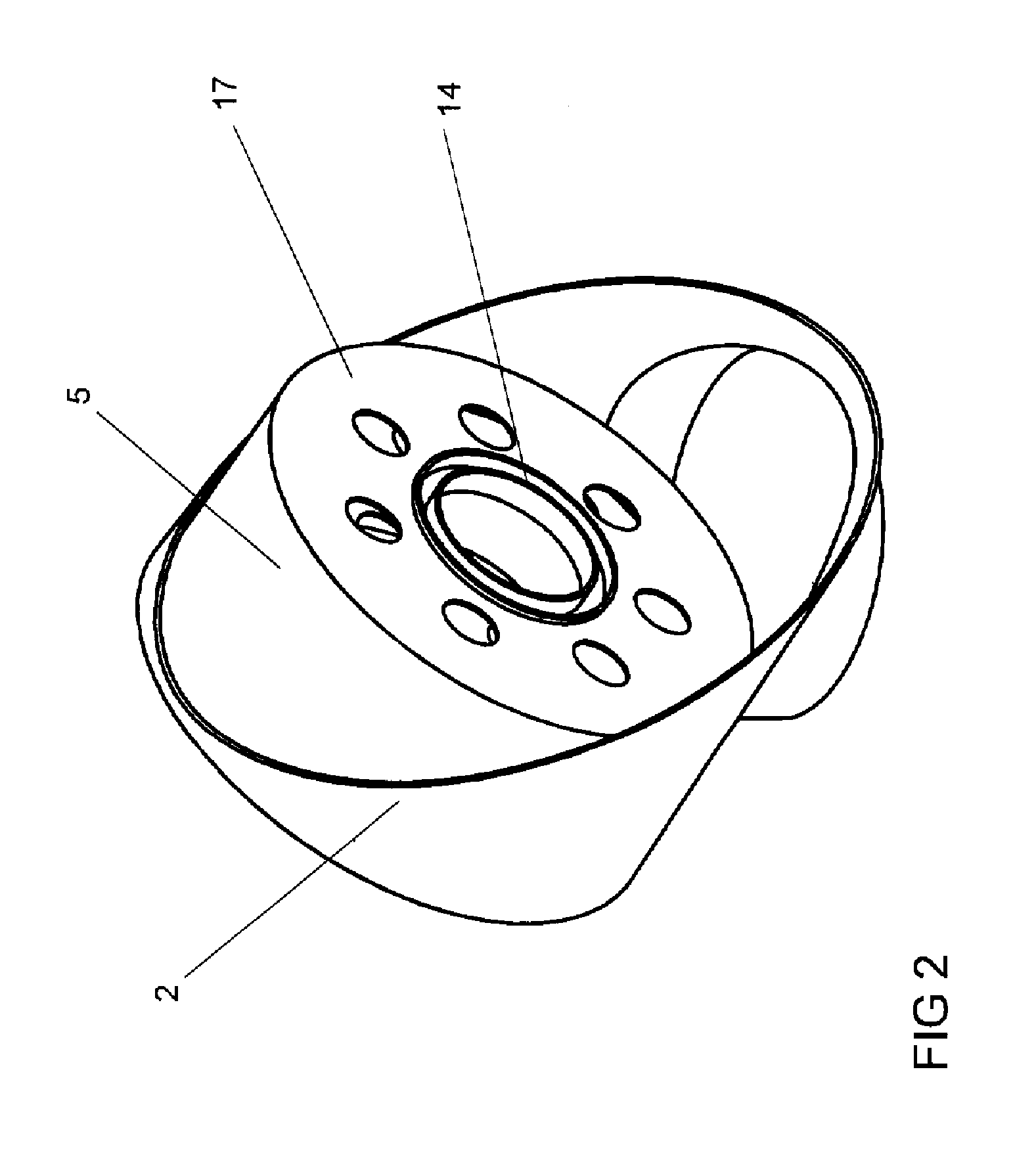
[0016]Generator part 3 is formed of the main shaft 4 and of a stator body 5.

[0017]The impeller head is connected to the main shaft 4 of the generator part 3 using a connection method known in the field of construction of wind power generators, wherefore this is not explained further hereunder. Furthermore, the impeller...


PUM


Abstract

This invention relates to an improved construction of wind power generator, the aim of which is to enhance the stability of the wind power generator and improve the balance between the generator and the tower, as well as to separate the generator from the function of the bearing structural part, enabling to direct the force generated in the turbine to the generator details.

Description

TECHNICAL FIELD[0001]The present invention relates, in general, to equipment for producing and storing wind power, and in particular, to an improved construction of wind power generator.DESCRIPTION OF RELATED ART[0002]There are several types of wind power generators, which comprise a base, a tower and a wind power generator fixed to the tower. The earlier wind power generator construction included a turbine connected to blades, a main shaft, a reducer and a generator part with a stator and a rotor. The kinds of generators present the problem of exhaustion caused by the transmission of main shaft-reducer-generator. Furthermore, such structure cannot be used for wind power generators that exceed the capacity of 1,500 kW as the torque generated by the main shaft and reducer becomes too excessive, and the construction suffers from exhaustion and material fatigue, which may result in damage to the structure.[0003]Another known solution of wind power generators is a reducer-free wind powe...

Claims


Application Information

Patent Timeline
Patent Type & Authority Applications(United States)
IPC IPC(8): F03D9/00
CPCF03D11/0008F05B2220/7066H02K7/1838Y02E10/722Y02E10/725Y02E10/721F03D80/70Y02E10/72F05B2240/50
Inventor SONAJALG, ANDRESSONAJALG, OLEG
Owner SONAJALG ANDRES
Why Eureka
Try Eureka