Stacked-type solid electrolytic capacitor capable of increasing welding effect and manufacturing method of the same

a solid electrolytic capacitor and manufacturing method technology, applied in the manufacture of electrolytic capacitors, capacitors, basic electric elements, etc., can solve the problems of limiting the electric capacity of products, affecting the number of capacitor units, affecting the mechanical strength and reliability of products, etc., to achieve the effect of increasing the welding effect and enhancing the air tightness of the package structur

Active Publication Date: 2018-09-18
APAQ TECH
View PDF6 Cites 1 Cited by
  • Summary
  • Abstract
  • Description
  • Claims
  • Application Information

AI Technical Summary

Benefits of technology

[0007]In view of the disadvantages of the existing art, the object of the instant disclosure is to provide a stacked-type solid electrolytic capacitor capable of increasing welding effect and the method for manufacturing the same, thereby avoiding the aluminum core being pushed out or splashed out during the welding process due to the compression of the anode parts of the capacitor. Therefore, the air-tightness property of the package structure is enhanced.
[0010]The instant disclosure at least comprises the following advantages. The method for manufacturing the stacked-type solid electrolytic capacitor employs the design of forming at least one buffering via-hole in the welding area of the anode part of each solid electrolytic capacitor unit in advance, then applying a welding current on the plurality of anode parts through the plurality of welding areas to form at least one welding joint between adjacent anode parts and hence, when the anode parts of the plurality of capacitor units are subjected to external force and compress each other during the welding process, the buffering via-hole provide stretching space for the core portion (such as aluminum core) of the anode parts to prevent the stress caused by the compression from destroying the structure of the anode part, and to avoid the core of the anode parts being pushed out or splashed out, and ensure the air-tightness of the product.

Problems solved by technology

Conventional liquid electrolytic capacitors cannot fulfill these requirement and hence, solid electrolytic capacitors have been developed.
However, in the welding process, the thickness of the anode parts of the capacitor units limits the possibility of success and the welding performance of the welding process, thereby affecting the number of the stack of the capacitor units and limiting the electric capacity of the products.
The mechanical strength and the reliability of the products are also affected.
In addition, when the anode part is subjected to external forces during the welding process, the anode parts compress each other and cause the aluminum cores to be pushed out or splashed out.

Method used


Image

  • Stacked-type solid electrolytic capacitor capable of increasing welding effect and manufacturing method of the same
  • Stacked-type solid electrolytic capacitor capable of increasing welding effect and manufacturing method of the same
  • Stacked-type solid electrolytic capacitor capable of increasing welding effect and manufacturing method of the same

Examples


first embodiment

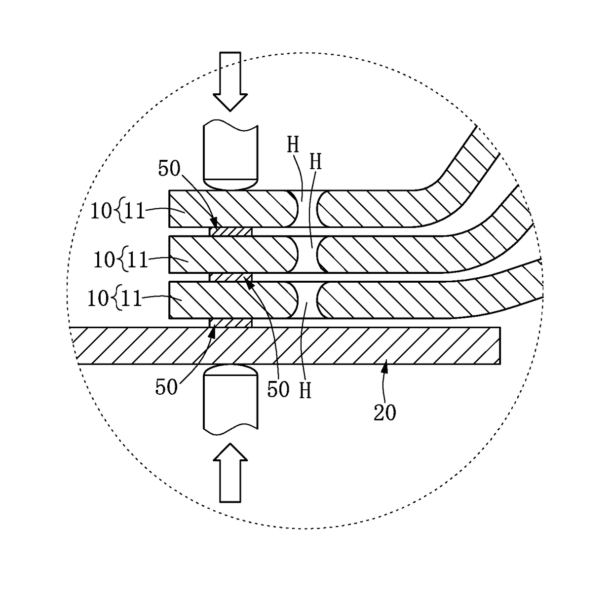
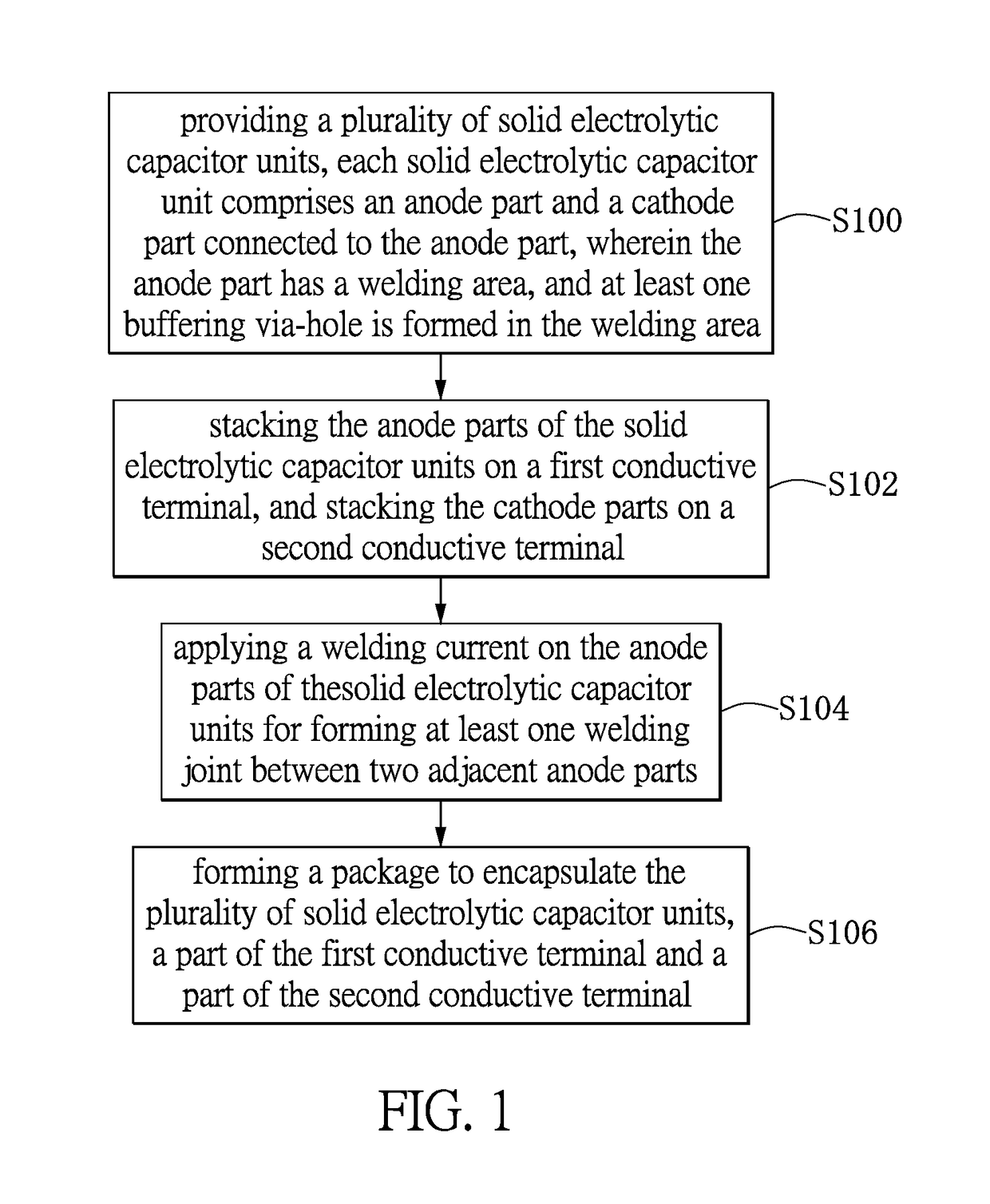
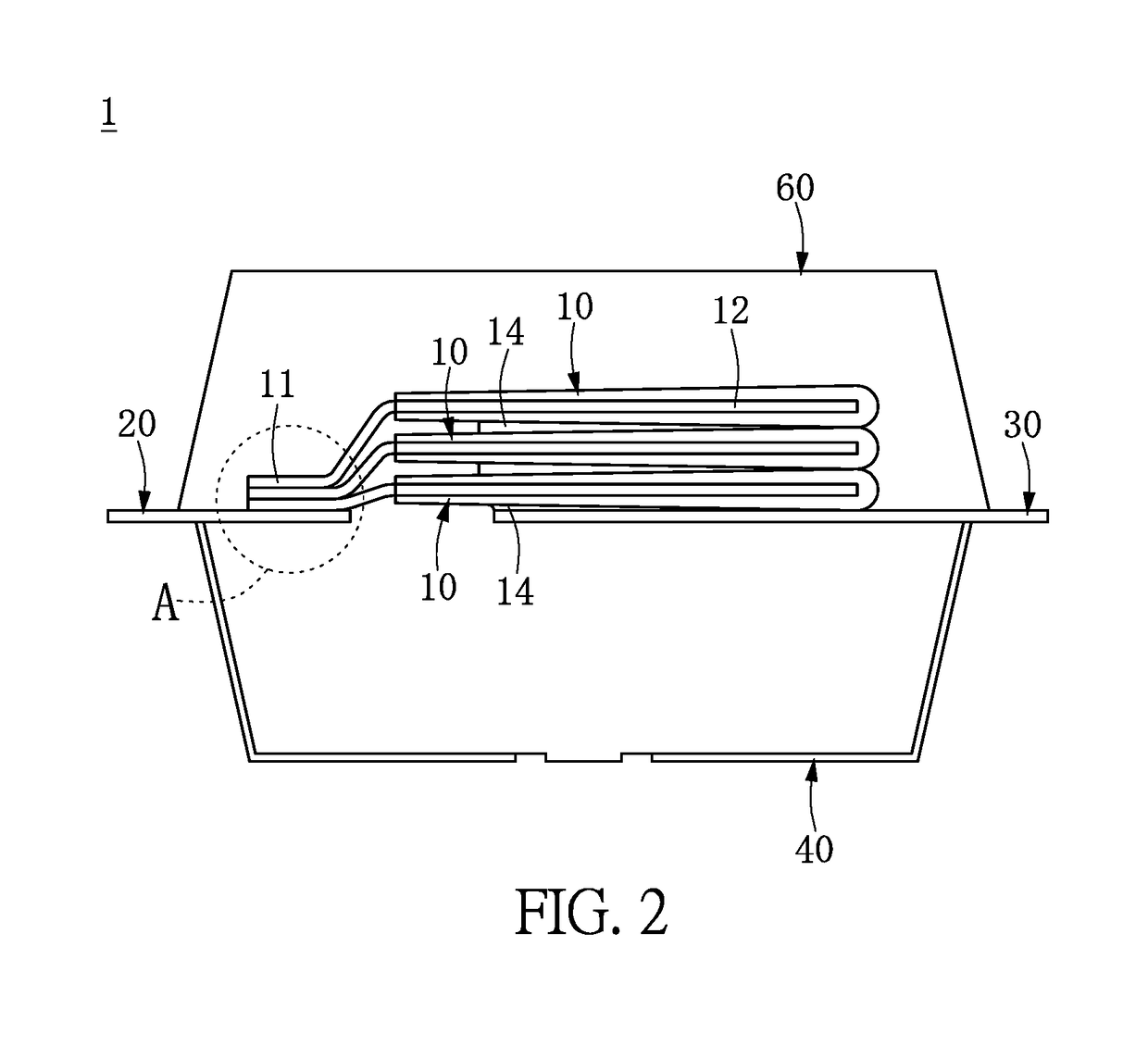
[0022]Please refer to FIG. 1. FIG. 1 is a flow chart of the method for manufacturing a stacked-type solid electrolytic capacitor capable of increasing welding effect of the first embodiment of the instant disclosure. Please refer to FIG. 2 to FIG. 7. The method for manufacturing the stacked-type solid electrolytic capacitor comprises step S100: providing a plurality of solid electrolytic capacitor units 10, each solid electrolytic capacitor unit 10 comprises an anode part 11 and a cathode part 12 connected to the anode part 11, the anode part 11 has a welding area 110, and at least one buffering via-hole H is formed in the welding area 110.

[0023]As shown in FIG. 2 to FIG. 4, the anode part 11 and the cathode part 12 are isolated and insulated from each other through an insulation layer 13. The anode part 11 comprises a first valve metal substrate 111 and a first corrosion layer 112 surrounding the outer surface of the first valve metal substrate 111. The cathode part 12 comprises a ...

second embodiment

[Second Embodiment ]

[0033]Please refer to FIG. 8. FIG. 8 is a flow chart of the method for manufacturing a stacked-type solid electrolytic capacitor capable of increasing welding effect of the second embodiment of the instant disclosure. The difference between the present embodiment and the first embodiment resides in the manner for welding the anode part 11 of the solid electrolytic capacitor unit 10 with the first conductive terminal 20.

[0034]Please refer to FIG. 9 and FIG. 10. The method for manufacturing a stacked-type solid electrolytic capacitor comprises the following steps. Step 200: providing a plurality of solid electrolytic capacitor units 10, each solid electrolytic capacitor unit 10 comprises an anode part 11 and a cathode part 12 connected to the anode part 11, in which the anode part 11 has a welding area 110 and at least one buffering via-hole H is formed in the welding area 110; step S202: stacking the anode parts 11 of the solid electrolytic capacitor units 10 on t...


PUM


Abstract

The instant disclosure relates to a stacked-type solid electrolytic capacitor capable of increasing welding effect and a manufacturing method of the same. The stacked-type solid electrolytic capacitor includes a plurality of solid electrolytic capacitor units, each of which has an anode part and a cathode part connected to the anode part, characterized in that the anode part is formed with at least one buffering via-hole in a welding area thereof. When each of the anode parts is compressed in a welding process, the volume of the corresponding buffering via-hole decreases accordingly. Therefore, the soldering performance of the anode part solid electrolytic capacitor is enhanced and the connection stability is increased.

Description

BACKGROUND[0001]1. Technical Field[0002]The instant disclosure relates to a manufacturing method of a stacked-type solid electrolytic capacitor, in particular, to a manufacturing method of a stacked-type solid electrolytic capacitor capable of increasing welding effect.[0003]2. Description of Related Art[0004]Capacitors are a necessary device in the electronic field, the main function thereof comprising: filtering, bypassing, rectifying, coupling, decoupling and phase inverting. Capacitors are widely used in consumer appliances, computer mother boards and related merchandise, power supplies, communication products and vehicles. Along with the development and improvement of the semiconductor processing techniques, the electronic products formed by semiconductor packages are developed based on the need of high compactness and accuracy. The electronic products must be small and compact, multi-function, and having high reliability. Conventional liquid electrolytic capacitors cannot fulf...

Claims


Application Information

Patent Timeline
Patent Type & Authority Patents(United States)
IPC IPC(8): H01G9/15H01G2/12H01G9/00H01G9/012H01G9/048H01G9/14H01G9/26
CPCH01G9/012H01G9/048H01G9/15H01G9/26H01G2/12H01G9/14H01G9/0029
Inventor CHEN, MING-TSUNGLIN, CHIEN-WEI
Owner APAQ TECH
Why Eureka
Try Eureka