
Forming and re-forming welding electrodes with contoured faces

a welding electrode and contoured face technology, applied in the field of welding electrodes, can solve the problems of difficult welding, affecting the welding effect of the electrode tip or welding face, and similar welding challenges, and achieve the effects of improving mechanical stability, easy fowling of new electrodes, and good alignmen

Active Publication Date: 2010-10-14
GM GLOBAL TECH OPERATIONS LLC
View PDF25 Cites 31 Cited by
  • Summary
  • Abstract
  • Description
  • Claims
  • Application Information

AI Technical Summary

Benefits of technology

This patent describes a new design for electrodes used in electrical resistance welding. The electrodes have a round cylindrical body with a tapered end to form a welding face. The welding face has concentric circular ridges or grooves that improve welding performance and can be easily restored for continued welding operations. The electrodes can be dressed to have a smooth surface and good alignment between the weld faces. The concentric ridges or grooves on the electrode face provide the benefits of both electrode dressing and texturing, including improved mechanical stability, low contact resistance, and reduced external expulsion. The electrodes can be easily prepared by machining grooves or ridges into a dressing blade and then using these grooves to produce corresponding ridges or grooves on the dressed surfaces of the electrode.

Problems solved by technology

Similar welding challenges arise in the welding of other light metal workpieces such as parts made of magnesium alloys.
The high electrical and thermal conductivity in combination with the insulating nature of the naturally-formed surface oxides of aluminum alloys (or magnesium alloys) makes them difficult to weld using spot welding practices previously developed for steel alloys.
But, whether textured or not, the tips or welding faces of the electrodes may be altered by erosion or by adhesion and buildup of workpiece material after numerous welds.
The redressing of grit blasted electrode faces, for example, can require many tens of seconds of off-line processing.

Method used


Image

  • Forming and re-forming welding electrodes with contoured faces
  • Forming and re-forming welding electrodes with contoured faces

Examples


Embodiment Construction

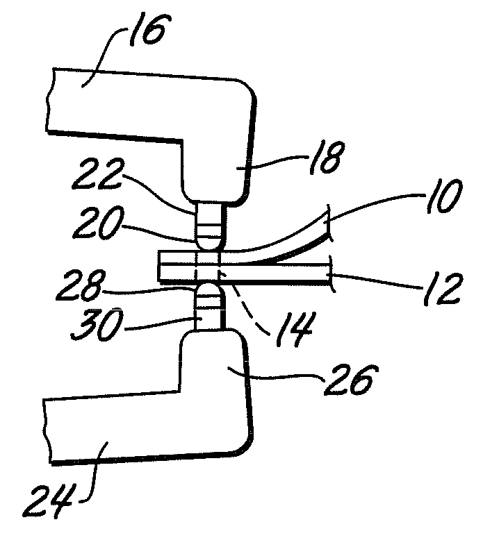
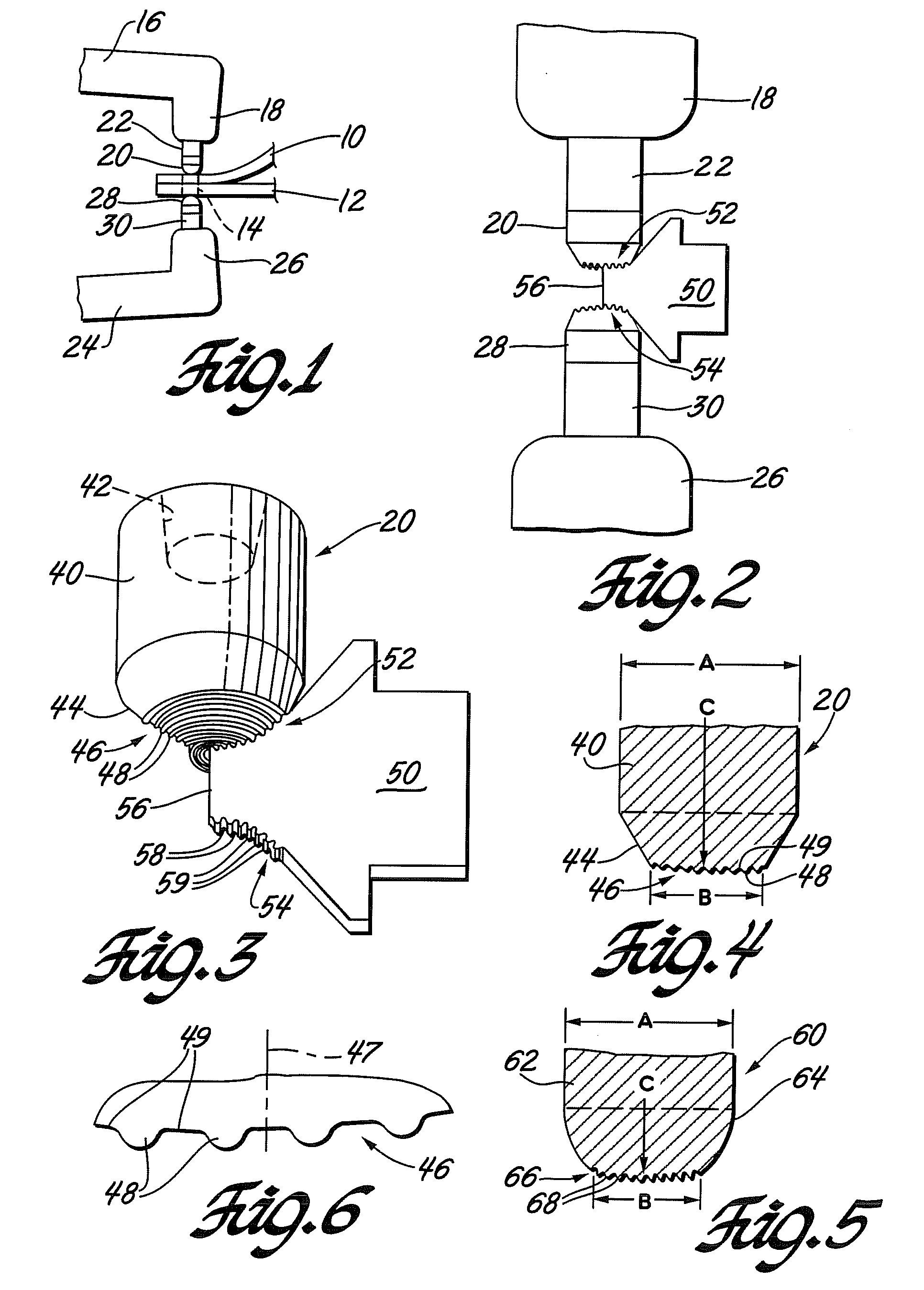
[0021]A welding electrode cap (or welding face) design is provided that is useful for forming spot welds in metal workpieces. The welding electrode cap is useful in spot welding operations generally, and it offers advantages for welding light metal workpieces such as aluminum alloy and magnesium alloy sheet materials. These materials often have an oxide film on surfaces contacted by the aligned and opposing electrodes and it is preferred that the electrode faces be shaped to engage and pierce the oxide film during welding.

[0022]In the manufacture of automotive doors, deck lids, liftgates, and the like, for example, it is often the practice to form these parts of complementary inner and outer sheet metal panels. The panels are of complex curvature for overall design effect and to contain any necessary electrical wiring and / or hardware between them. The formed panels usually have flanges at their peripheral edges for joining. An inner panel is placed against an outer panel and the ass...


PUM

PropertyMeasurementUnit
heightsaaaaaaaaaa
heightsaaaaaaaaaa
heightsaaaaaaaaaa

Abstract

A method is disclosed for using welding electrodes with a spherically-domed welding face having concentric contoured features formed into the face for better contact with workpiece surfaces. The concentric contoured features may be initially formed by rotating a cutting tool with a contoured cutting edge, the cutting edge being in engagement with the electrode face. A similar practice may be followed to re-create the weld face surface geometry if it becomes eroded or malformed during welding use. A suitable tool may have a blade-like geometry, with a mounting portion for supporting and positioning the tool in a rotating holder and a cutting edge. The cutting edge may have a contour complementary to that of the weld face and extend at least from the center of the weld face to at least the radial extent of the concentric contoured features.

Description

[0001]This application is a division of Ser. No. 11 / 536,001 filed Sep. 28, 2006.TECHNICAL FIELD[0002]This invention pertains to welding electrodes for electrical resistance welding. More specifically this invention pertains to the formation of concentric geometric features on the welding face of the electrode for improved electrical contact with the workpiece.BACKGROUND OF THE INVENTION[0003]Current automotive vehicle manufacturing operations include, for example, the joining of two or three sheet metal layers by resistance spot welding. Vehicle body panels such as doors, hoods, deck lids and liftgates are often assembled by joining inner panels, outer panels, and various reinforcements stamped from sheet metal of suitable metal alloys. Ferrous or aluminum alloys are often used. The thickness of each sheet metal layer may vary from less than one millimeter to more than four millimeters. Electrical resistance spot welding is often used to join such inner and outer panels or other met...

Claims


Application Information

Patent Timeline
Patent Type & Authority Applications(United States)
IPC IPC(8): B23K11/00B26D1/12
CPCB23B5/166B23K11/3009Y10T82/16442B23K35/0205Y10T407/19B23K11/3063B23K11/14Y10T83/9372
Inventor SIGLER, DAVID R.KARAGOULIS, MICHAEL J.
Owner GM GLOBAL TECH OPERATIONS LLC
Learn More