Airflow cooling lid

a cooling lid and airflow technology, applied in the field of beverage containers, can solve the problems of slow change in this field, possible spillage, and burning of consumers' lips, mouths, and torsos from hot coffee, tea and other beverages, and achieve the effect of rapid and personalized optimal temperature for consumption, simple, effective, safe and convenient control

Active Publication Date: 2018-05-22
SHAPIRO AKIVA
View PDF32 Cites 3 Cited by
  • Summary
  • Abstract
  • Description
  • Claims
  • Application Information

AI Technical Summary

Benefits of technology

[0014]At the heart of the present invention is my discovery that another source of scalding is that economically produced lids provide no uncomplicated method for the consumer to simply, effectively, inexpensively, safely, and conveniently finely control the rate at which the liquid temperature decreases, thereby achieving a rapid and personalized optimal temperature for consumption.
[0015]In accordance with the invention, then, a lid is provided which allows the consumer, in one economical configuration, to blow air across the contents to cool it, and sip liquid contents, with ease.
[0017]The present embodiment is a beverage lid that empowers the consumer to simply, effectively, inexpensively, safely, and conveniently finely control the rate at which the liquid temperature decreases, thereby achieving a rapid and personalized optimal temperature for consumption.
[0018]Typically, in order to accelerate cooling a hot beverage, the consumer will either dilute the beverage by adding cold water, ice or more milk than desired, thereby reducing the palatability of the beverage, or open the container to let the beverage cool down, which is often impractical and can result in a messy spillage causing skin burns or clothing stains. Other prior art, not widely in use, as described above, may also enable faster cooling, albeit at the price of a complicated apparatus that is bulky, expensive to produce, and / or inconvenient and potentially unsafe—especially when driving.
[0019]The present embodiment describes an improved lid for hot beverage containers that enables the user to cool down the hot beverage without removal of the lid by blowing air across the surface of the beverage. Adding an adequately sized and appropriately positioned exhaust opening creates an escape route for high-humidity hot air, allowing it to be displaced by low-humidity cooler air blown into the other opening. The embodiment is elegant, as simple to manufacture as the current market dominant lid configurations, cost effective, and convenient.

Problems solved by technology

Consumers burning their lips, tongue, mouth, arms, legs, and torso from hot coffee, tea and other beverages continues to be a problem.
Change in this field has been slow.
Reservoir cooling suffers firstly, from requiring the beverage to initially escape from the inner portion of the container, thereby creating a possibility of spillage as there is nothing to prevent overflow.
Thirdly, the container needs to be constantly tipped upward, which is both impractical and dangerous in driving applications.
And fourthly, the process of manufacture is significantly more complicated and costly.
Heat transfer at the point of consumption cooling suffers firstly, from the fluid consumed during the initial stage of each sip cannot be sufficiently cooled as the cooling airflow is yet to be drawn over the liquid.
Bellows cooling suffers firstly, from a mechanically complex device, which significantly increases the cost of manufacturing.
Secondly, it is bulky, which, in turn, negatively affects the cost of stacking, storage and transportation.
And thirdly, and more importantly, the device is unsafe for driving applications as it requires the user to use both hands: one hand to hold the cup and the other to push the bellows.
Ridge cooling suffers firstly, from a mechanically complex device, which increases the cost of manufacturing.

Method used


Image

  • Airflow cooling lid
  • Airflow cooling lid
  • Airflow cooling lid

Examples


Embodiment Construction

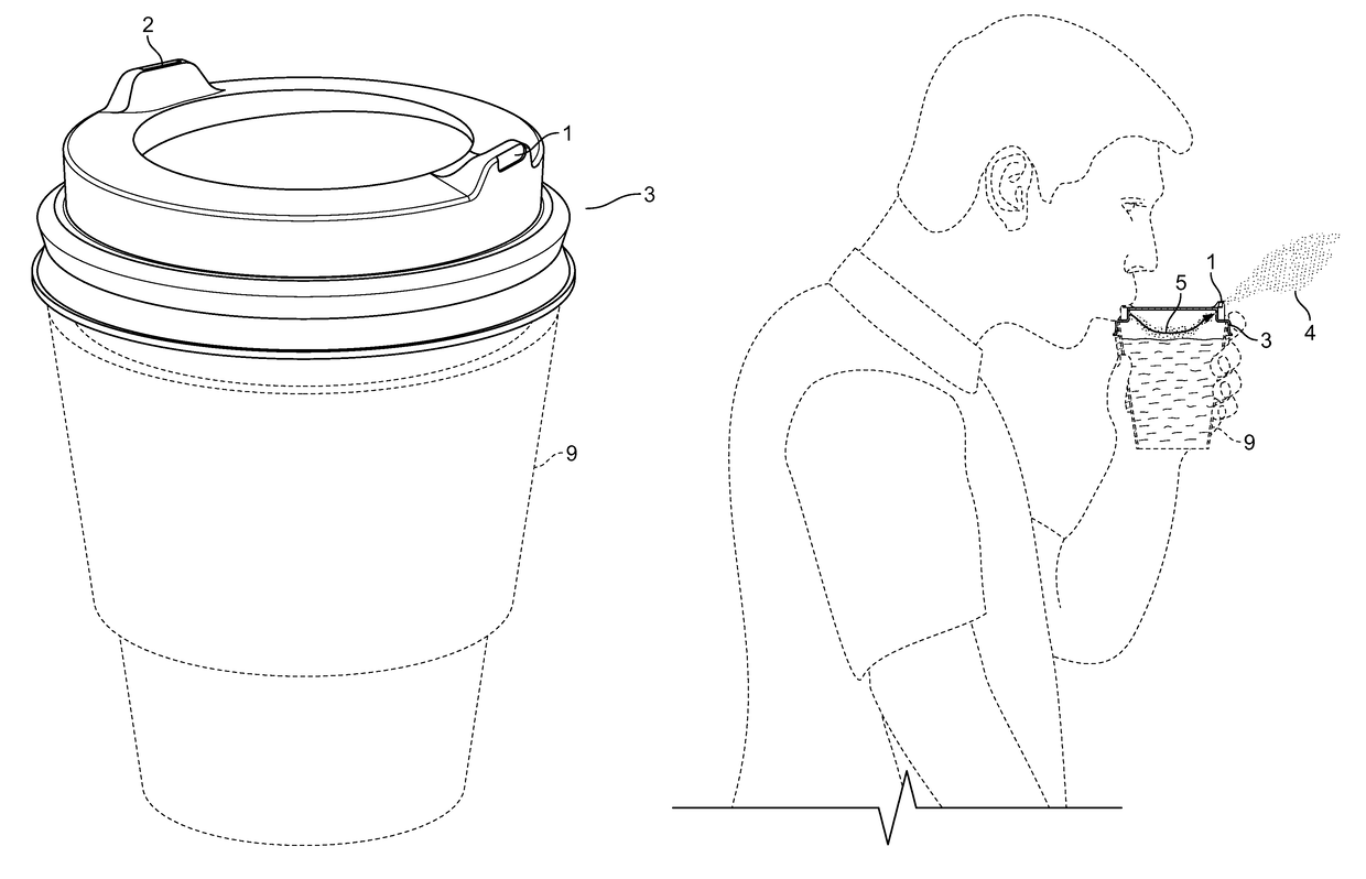
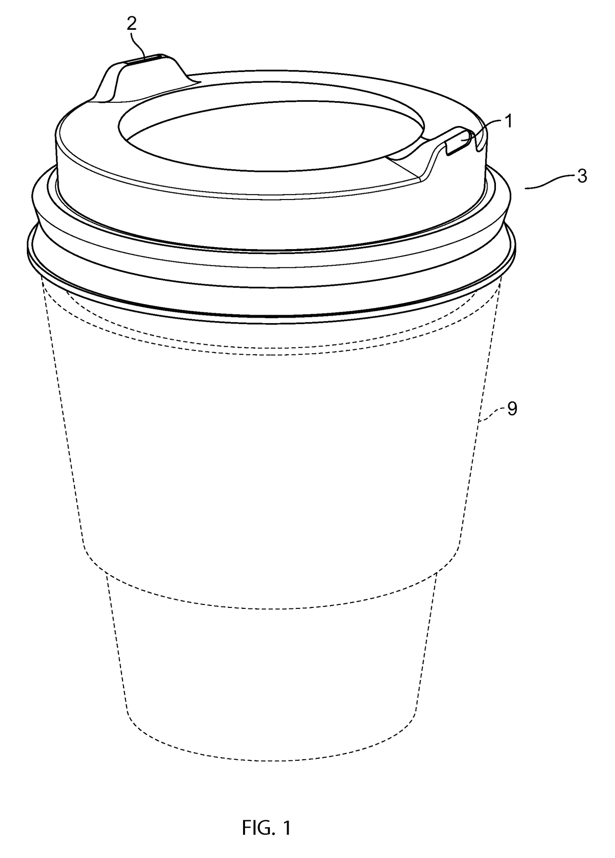
[0026]Referring to FIG. 1-5.

[0027]Cup, 9, is shows for exemplary purposes and is disclaimed.

[0028]One exemplary mode of carrying out the embodiment, though not exclusively, is manufacture of the lid, substantially as depicted in FIG. 1. At present I believe that this embodiment operates most efficiently, but other embodiments are also satisfactory.

[0029]With lids having sidewalls, 3 of FIG. 1, the exhaust opening, 1, may be placed on the sidewall or onto the upper surface of the lid diagonally opposite to the drinking opening, 2, or in any convenient location to achieve the result. With lids having no sidewalls, FIG. 5, the exhaust opening, 1, is placed onto the upper surface of the lid diagonally opposite to the drinking opening or in any convenient location to achieve the result.

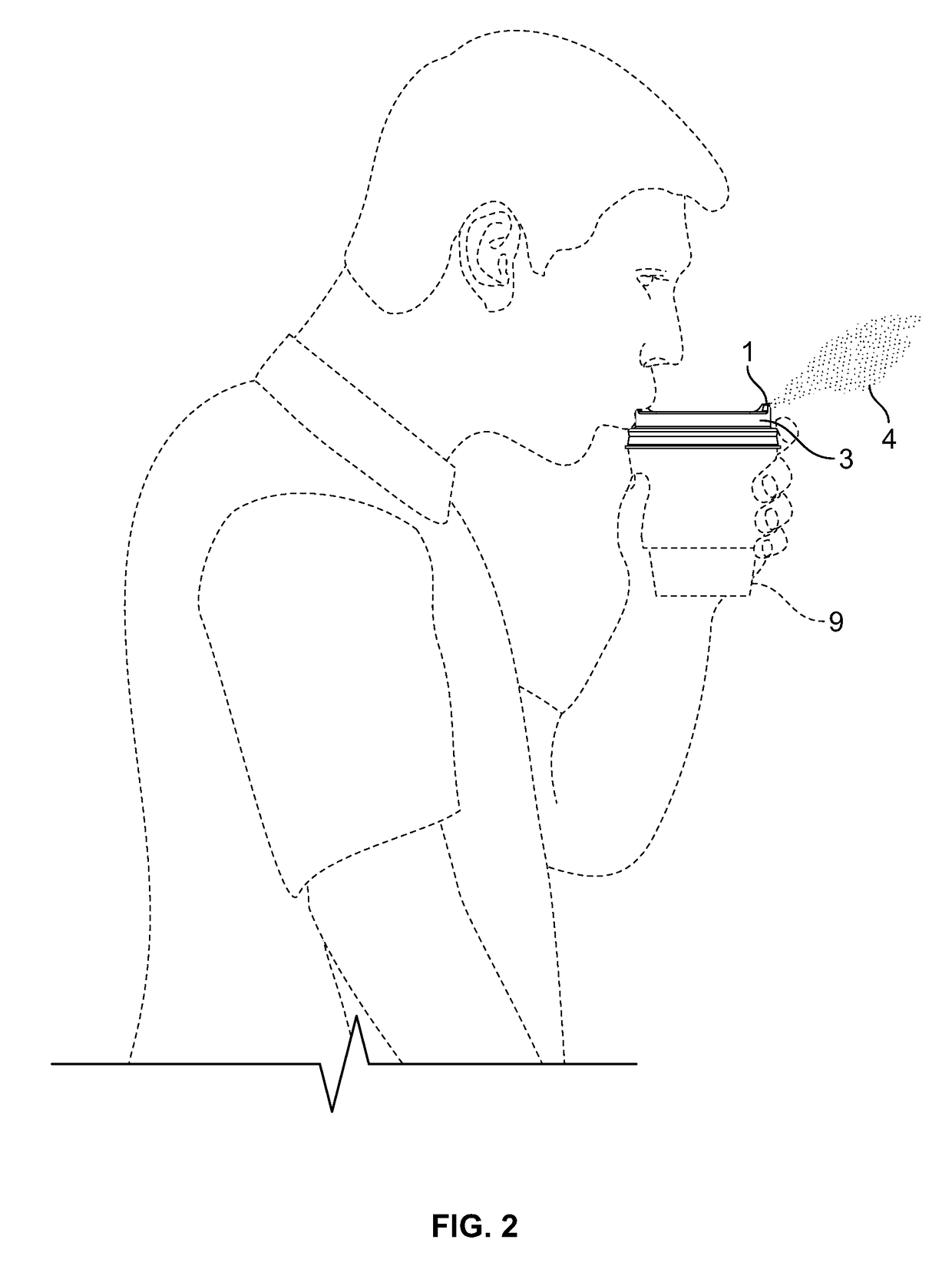
[0030]One variation is to angle either or both openings so as to direct the driven exhaust, 4, away from the face of the consumer, as depicted in FIG. 2 AND FIG. 3.

[0031]As noted, depending on the embodime...


PUM


Abstract

In the field of lids for beverage containers, an airflow cooling lid for hot beverage containers that enables the user to cool down the beverage in the container by blowing outside air across the surface of the beverage without removal of the lid. The airflow cooling lid comprises a circular cover snuggly placed over a hot beverage container having a mounting rim, a surface portion, a drinking opening in form of an opening for consuming the beverage and an exhaust opening to be used as either the intake or exhaust portal for the air drawn over the surface of the beverage. Either or both the drinking opening or the exhaust opening may be angled outward to allow the exhaust air to flow away from the face when blowing through either portal.

Description

[0001]The following is a description of the invention provided to aid those skilled in the art in practicing in the field of the present invention. Those of ordinary skill in the art may make modifications and variations in the embodiments described herein without departing from the spirit or scope of the present invention. Unless otherwise defined, all technical and scientific terms used herein have the same meaning as commonly understood by one of ordinary skill in the art to which this invention belongs. The terminology used in the description of the invention herein is for describing particular embodiments only and is not intended to be limiting of the invention. All publications, patent applications, patents, figures and other references mentioned herein are expressly incorporated by reference in their entirety.TECHNICAL FIELD[0002]The present invention is generally in the technical field of beverage containers, and, more particularly, is in the field of lids for beverage conta...

Claims


Application Information

Patent Timeline
Patent Type & Authority Patents(United States)
IPC IPC(8): A47G19/22B65D51/16B65D43/02B65D43/16B65D21/02
CPCB65D51/1611A47G19/2272B65D21/02B65D43/02B65D43/16B65D2543/00296B65D2251/0021B65D2543/00046B65D2543/00092B65D2543/00277B65D2251/009B65D43/0202B65D2543/00305B65D2543/00537
Inventor SHAPIRO, AKIVA
Owner SHAPIRO AKIVA
Why Eureka
Try Eureka