
Nozzle of a gas burner

a gas burner and nozzle technology, applied in the direction of burners, combustion types, combustion processes, etc., can solve the problems of red flames, damage to the gas burner, and the non-combustion of a portion of the gas/air mixture, etc., to achieve the effect of being cheap and effectiv

Inactive Publication Date: 2010-08-05
LIOU JIN CHIH
View PDF4 Cites 9 Cited by
  • Summary
  • Abstract
  • Description
  • Claims
  • Application Information

AI Technical Summary

Benefits of technology

[0008]It is the primary objective of the present invention to provide an inexpensive and effective nozzle for a gas burner.

Problems solved by technology

The rectilinear manner of the travel of the gas / air mixture entails problems.
Firstly, a portion of the gas / air mixture is dissipated without combustion because it travels too fast and too far after leaving the nozzle.
Secondly, undesirable red flames, which damage the gas burner faster than blue flames, are produced by combustion of the gas / air mixture because of inadequate time for mixing the gas with the air in the nozzle.
The equipment of the nozzle with the addition helical element inevitably increases cost and time for making and assembling parts.

Method used


Image

  • Nozzle of a gas burner
  • Nozzle of a gas burner
  • Nozzle of a gas burner

Examples


Embodiment Construction

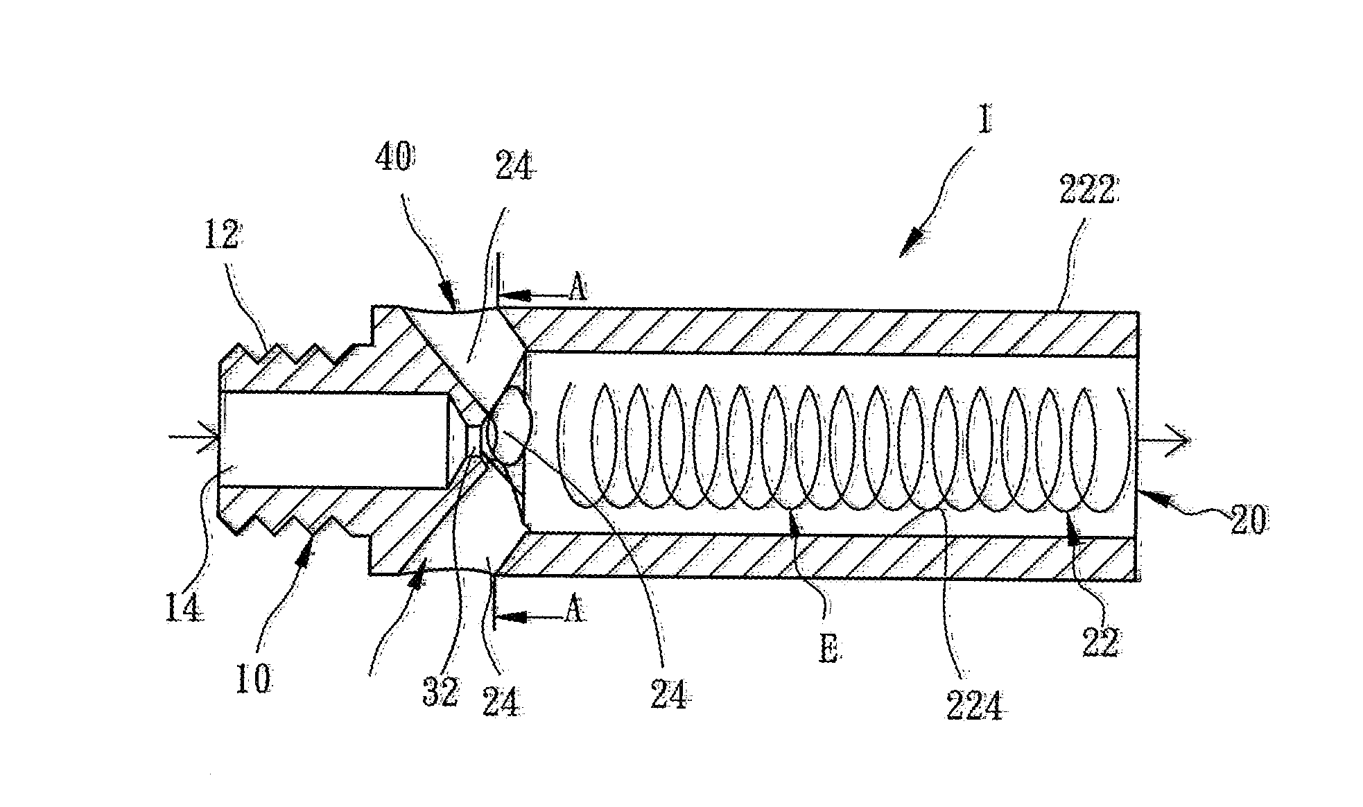
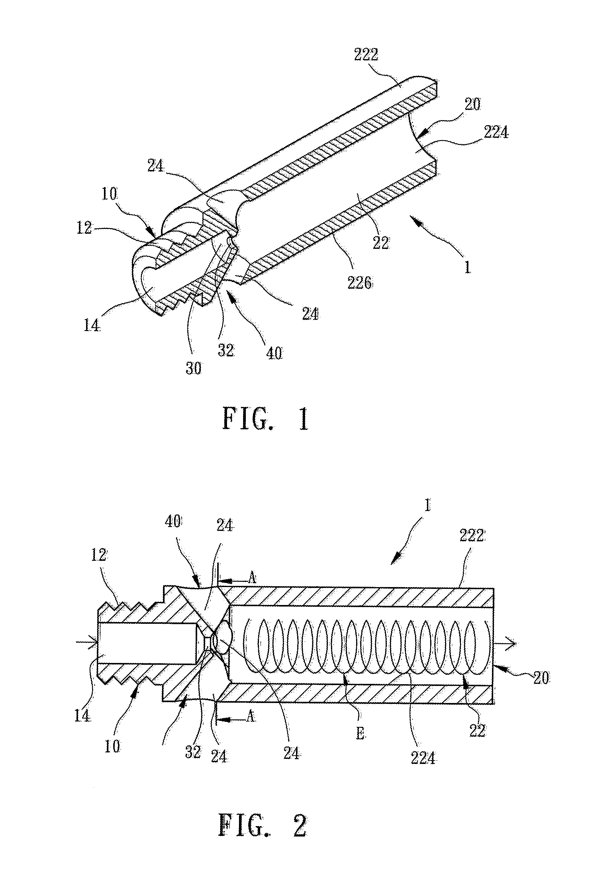
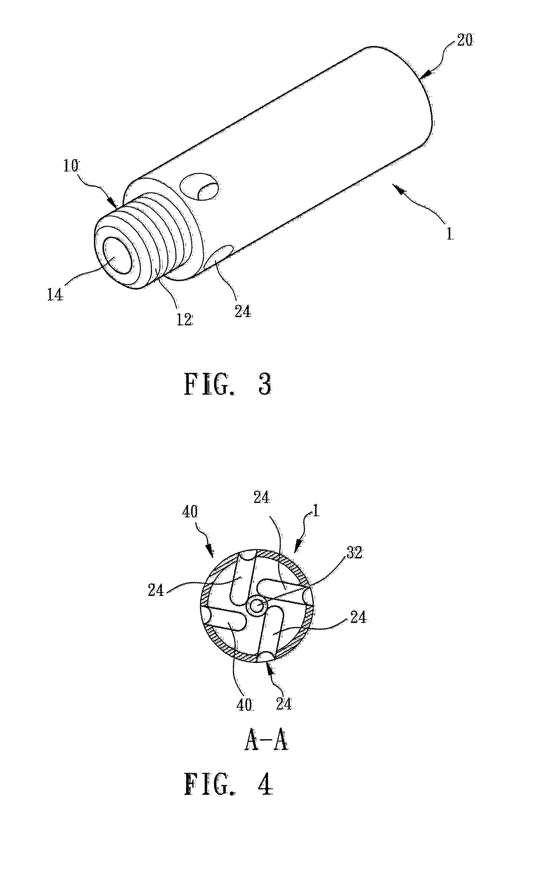
[0017]Referring to FIGS. 1 and 3, a nozzle 1 includes a joint section 10 and an outlet section 20 extended from the joint section 10 along an axis according to a first embodiment of the present invention. Obviously, the nozzle 1 is hollow throughout its length along the axis. A thread 12 is formed on an external side of the joint section 10. The thread 12 can be engaged with a thread formed on an internal side of a gas cock. A gas inlet channel 14 is defined in the joint section 10 along the axis. The outlet section 20 can be connected to a pipe of a gas burner.

[0018]The outlet section 20 includes a gas / air mixture channel 22 defined therein along the axis. Therefore, the outlet section 20 includes an external side 222 and an internal side 224 spaced from each other along a radius perpendicular to the axis. A wall 226 of the outlet section 20 is delimited by and between the external side 222 and the internal side 224. The wall 226 is made of proper thickness. An annular rib 30 is fo...


PUM


Abstract

A gas burner is provided with a nozzle. The nozzle includes a joint section, an annular rib, an eddy-producing device and an outlet section along an axis. The joint section includes a gas inlet channel defined therein along the axis. The outlet section extends from the joint section. The outlet section includes a wall made of adequate thickness and formed between an external side and an internal side along an axis in perpendicular to the axis. A gas / air mixture channel is defined in the wall along the axis. The eddy-producing device includes air inlet channels each extending throughout the wall not along a radius in perpendicular to the axis. The annular rib extends on the internal side of the outlet section and includes an aperture through which the gas inlet channel is in communication with the gas / air mixture channel.

Description

BACKGROUND OF INVENTION[0001]1. Field of Invention[0002]The present invention relates to a gas burner and, more particularly, to a nozzle of a gas burner for producing an eddy current of gas / air mixture to improve combustion of the gas / air mixture.[0003]2. Related Prior Art[0004]A gas-operated water heater or a tabletop cooking device includes at least one gas burner with at least one nozzle. Generally, such a nozzle provides gas / air mixture in a rectilinear manner. The rectilinear manner of the travel of the gas / air mixture entails problems. Firstly, a portion of the gas / air mixture is dissipated without combustion because it travels too fast and too far after leaving the nozzle. Secondly, undesirable red flames, which damage the gas burner faster than blue flames, are produced by combustion of the gas / air mixture because of inadequate time for mixing the gas with the air in the nozzle.[0005]To overcome the foregoing problems, the applicant of the present application finished a noz...

Claims


Application Information

Patent Timeline
Patent Type & Authority Applications(United States)
IPC IPC(8): F23D14/48B05B7/06
CPCF23D14/64F23D14/48
Inventor LIOU, JIN-CHIH
Owner LIOU JIN CHIH
Learn More