Solar thermal heating utilizing dynamic particle flow balancing

a technology of solar thermal heating and dynamic particle flow, applied in the safety of solar heat collectors, solar heat collector details, light and heating apparatus, etc., can solve the problems of high cost of solar thermal panels for home heat applications, many panels are required, and the use of thermal solar devices is not usually used to heat the house. to achieve the effect of reducing the cost of solar thermal panels

Inactive Publication Date: 2011-01-13
KNOWM TECH
View PDF13 Cites 9 Cited by
  • Summary
  • Abstract
  • Description
  • Claims
  • Application Information

AI Technical Summary

Benefits of technology

[0017]A solar thermal panel is thus disclosed, which is based on liquid-particle dynamics, and which can reduce the cost of solar thermal panels by 75% or more. When fluid is pumped through the panels they become black and highly absorbent. When fluid is not circulating the panels become highly reflective. The overheating-prevention mechanism allows for the construction of an all-plastic solar thermal panel. A prototype panel has been constructed from commonly available materials to validate the principle.

Problems solved by technology

Such thermal solar devices are not usually utilized to heat the house.
A major problem with using solar thermal water heating to heat a house is that many panels are required during the winter to produce the heat needed.
Another significant problem is that the cost of solar thermal panels for a home heat application is high, since a large number is required.
Such systems present the significant problem of dissipating the waste heat generated by the solar collectors.
This is, however, an expensive solution.
This is not ideal and even dangerous, as it leaves open the possibility that one could forget to cover the collectors or may simply be unable to perform for the task.
This is also an expensive solution and is prone to breakage due to motor failure or wind drag, which causes wear on the gear assembly.
However, there remains the problem of finding a stable black heat transfer fluid that will not damage the pump and the problems and potential huge mess of a leak.
After many uses, it is quite possible that the black liquid will stain the inside of the panel, leading to original problems of overheating during non-use.
In addition, the panels may require a large pump, as a closed-loop circulation is not possible.
This approach, however, results in a number of problems.
The problem results in shutting it off when it is desired to stop heating.
In this case, there is no method to prevent high stagnation temperatures, which could lead to the circulation fluid boiling, the panels melting, wood catching on fire, etc.
Although the material and article of U.S. Patent Application No. 20070210287 could be used in, for example, airplane windows, but is not suitable for use in solar thermal heating applications.
The problem, again, with such a device is how does one actually turn the panel off?
Because the absorber is built into the panel, there is not a practical and safe method or apparatus for turning the panel off when one does not desire to collect heat.
Although solar thermal energy provides an abundant source of energy for heating, unfortunately most households utilize fossil fuels to provide heat.
Unfortunately our society has been shortsighted in this respect and we have the problem of heating millions of incredibly inefficient homes.
A significant problem with plastic, however, is that exposure to high temperatures may degrade or deform the material, rendering the panels useless.
However, the insulation can lead to extremely high temperatures within the collector if the heat is not removed.
If a pump fails, the electricity goes out, or a blockage forms in the circulation path, the circulation will stop and the temperature will rise in the panels.
This is a significant problem currently inhibiting the use of plastic as a source of solar heat generation.

Method used


Image

  • Solar thermal heating utilizing dynamic particle flow balancing
  • Solar thermal heating utilizing dynamic particle flow balancing
  • Solar thermal heating utilizing dynamic particle flow balancing

Examples


Embodiment Construction

[0034]The particular values and configurations discussed in these non-limiting examples can be varied and are cited merely to illustrate an embodiment of the present invention and are not intended to limit the scope of the invention. Note that in FIGS. 1-6, identical or similar parts or elements are generally indicated by identical reference numerals.

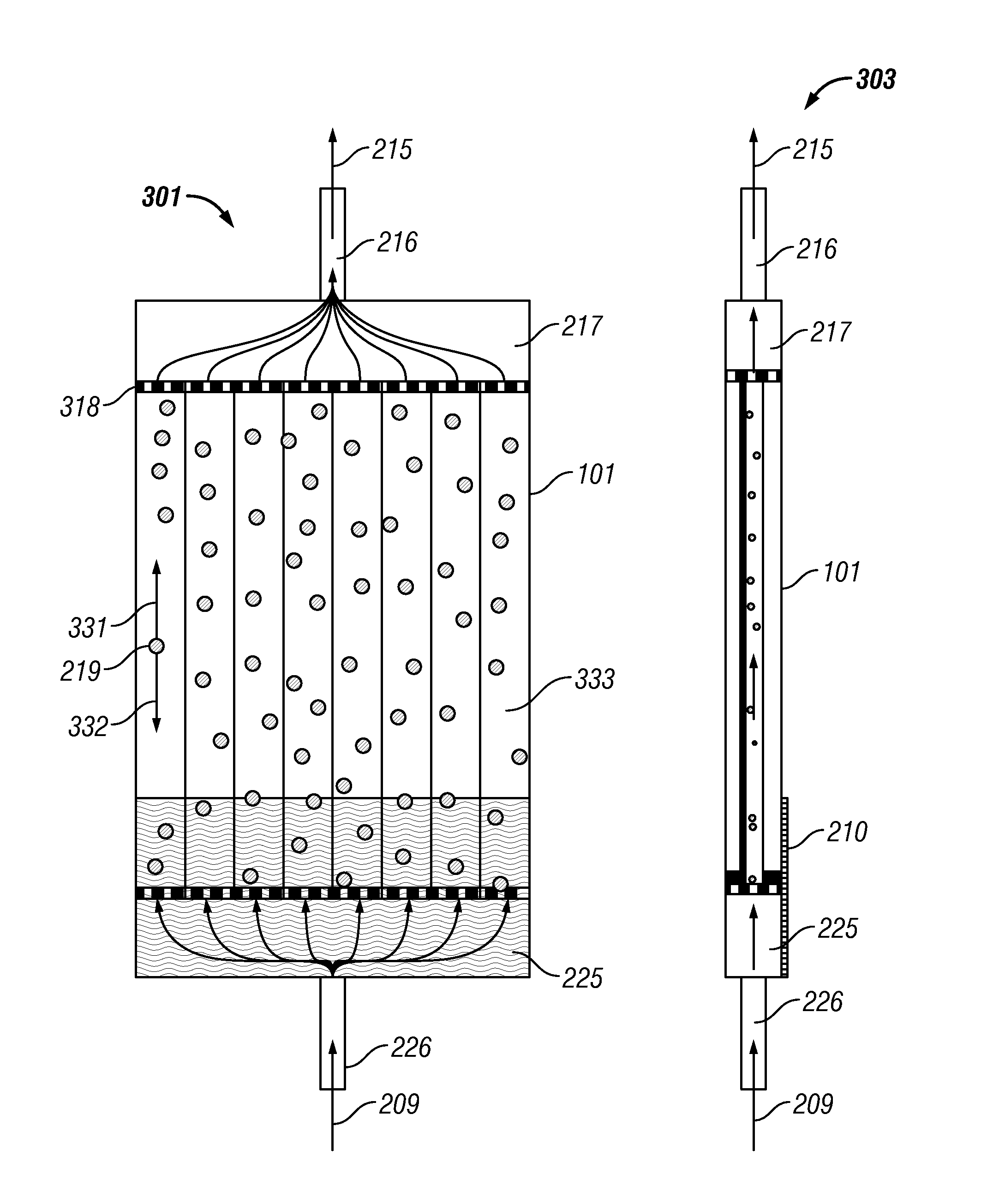
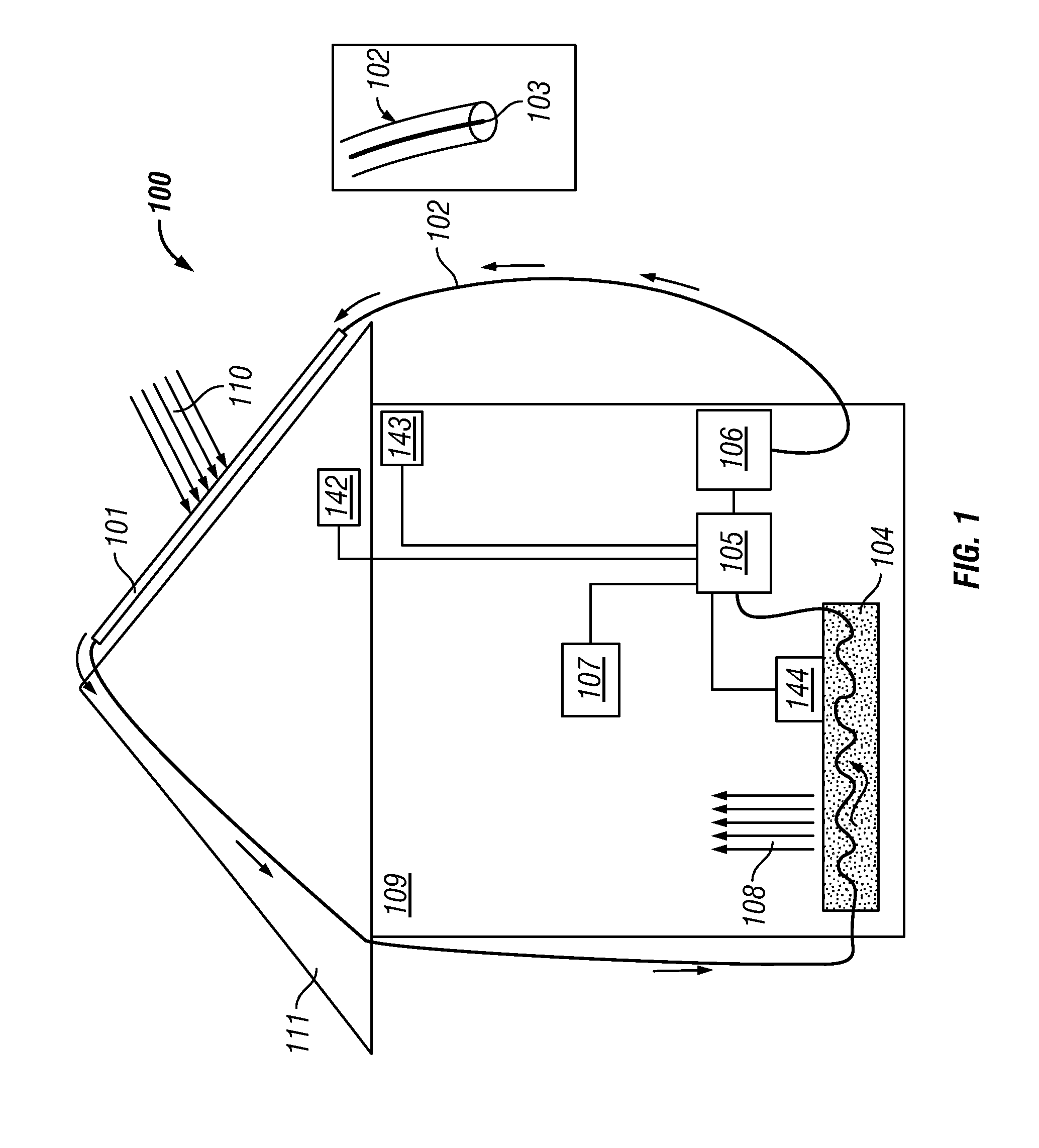
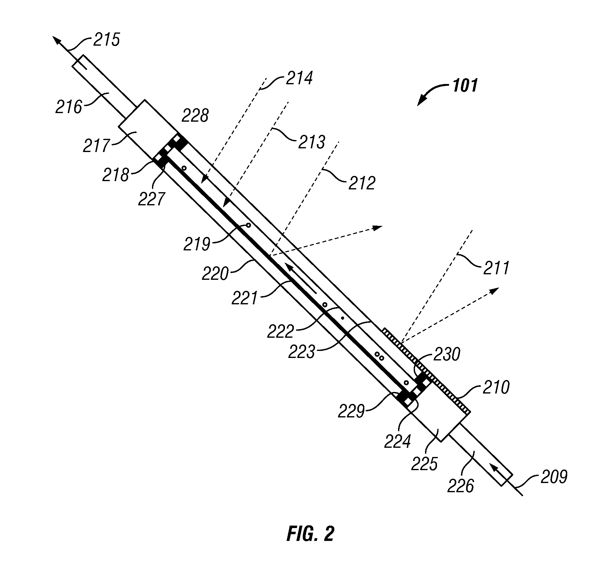
[0035]FIG. 1 illustrates a heating system 100, in accordance with an embodiment. In the configuration of system 100, a building 109 generally includes a roof 111 upon which a thermal solar panel 101 is located. Light (as indicated by arrows 110) impinges on the panel 101, where it is absorbed as heat by particles 219 suspended in a liquid that flows through the panel 101 in a direction against the force of gravity. Note that the particles 219 can be, for example, but not limited to silicon carbonate particles.

[0036]The liquid is circulated through a heat mass 104, through a controller 105, and finally through a circulation pump 106. A c...


PUM


Abstract

A solar heating apparatus, which includes a panel having one or more layers or a group of such layers, wherein one or more layers among such a group of layers constitutes a transparent medium. The panel includes at least two other layers among the group of layers, which constitute a reflective medium. The panel additionally includes one or more spaces formed between the layers and at least one other space formed between the other layers. A heat transfer fluid can be located within the space between the layers. The heat transfer fluid contains heat-absorbing particles, which are suspended in the heat transfer fluid and subject to a flow-force through the panel in a direction against a force of gravity. The heat-absorbing particles are held in light in the panel via a balance of a flow-force and the force of gravity. The heat-absorbing particles drift to the bottom of the panel when the flow-force stops.

Description

CROSS-REFERENCE TO PROVISIONAL PATENT APPLICATION[0001]This patent application claims the benefit under 35 U.S.C. §119(e) of U.S. Provisional Application Ser. No. 61 / 224,780 entitled, “Solar Heating Utilizing Dynamic Particle Flow Balancing,” which was filed on Jul. 10, 2009 and is incorporated herein by reference in its entirety. This patent application further claims the benefit under 35 U.S.C. §119(e) of U.S. Provisional Application Ser. No. 61 / 293,688 entitled, “Solar Heating Utilizing Dynamic Particle Flow Balancing,” which was filed on Jan. 10, 2010 and is incorporated herein by reference in its entirety.TECHNICAL FIELD[0002]Embodiments relate to solar energy and solar heating applications. Embodiments also relate to solar thermal heating panels and associated devices and components.BACKGROUND[0003]Solar energy is an attractive source of energy for heating, for example, a home or office building. Solar thermal devices are currently employed in some homes and other buildings to...

Claims


Application Information

Patent Timeline
Patent Type & Authority Applications(United States)
IPC IPC(8): F24J2/48F24J2/04
CPCF24J2/1057F24J2/201F24J2/42F24J2/4621Y02E10/44F24J2/48F24J2/50F24J2002/1061Y02B10/20F24J2/4649F24S10/501F24S23/82F24S40/50F24S70/10F24S80/20F24S80/56F24S90/00F24S2023/84
Inventor NUGENT, ALEX
Owner KNOWM TECH
Why Eureka
Try Eureka