Flexible transport auger

a technology of flexible transport and auger, which is applied in the field of flexible transport auger, can solve the problems of nerve irritation and pain, affecting the flow of waste products out of the disc, and causing the cell within the nucleus pulposus to emit toxic amounts of cytokines and mmps,

Active Publication Date: 2018-05-29
MEDOS INT SARL
View PDF310 Cites 11 Cited by
  • Summary
  • Abstract
  • Description
  • Claims
  • Application Information

AI Technical Summary

Benefits of technology

[0011]The present invention relates to a flexible hollow auger for low-torque transmitting drive shafts, which allows for effective tissue material transport through curved, flexible tubes and channels.
[0012]In one embodiment, the present invention describes a hollow flexible auger. An hollow auger has a hollow center, so that the helical member hugs the inner wall of an outer tube. In use, material is transported along both the center axis and the inner wall of the tube. The hollow flexible auger allows for transportation of material from an operative location in the patient (material removal) as well as to an operative location in the patient (material delivery).
[0014]This design has the potential of providing very low manufacturing costs, which could present an economic advantage in single-use applications. The present invention is especially designed for use in transporting excised material from an intervertebral disc, but could find application in other medical areas in which transportation of solid or liquid material along a curved or flexible tube or channel is desired.

Problems solved by technology

In other instances of DDD, genetic factors or apoptosis can also cause the cells within the nucleus pulposus to emit toxic amounts of these cytokines and MMPs.
In some instances, the pumping action of the disc may malfunction (due to, for example, a decrease in the proteoglycan concentration within the nucleus pulposus), thereby retarding the flow of nutrients into the disc as well as the flow of waste products out of the disc.
This reduced capacity to eliminate waste may result in the accumulation of high levels of toxins that may cause nerve irritation and pain.
As DDD progresses, toxic levels of the cytokines and MMPs present in the nucleus pulposus begin to degrade the extracellular matrix, in particular, the MMPs (as mediated by the cytokines) begin cleaving the water-retaining portions of the proteoglycans, thereby reducing its water-retaining capabilities.
This degradation leads to a less flexible nucleus pulposus, and so changes the loading pattern within the disc, thereby possibly causing delamination of the annulus fibrosus.
These changes cause more mechanical instability, thereby causing the cells to emit even more cytokines, thereby upregulating MMPs.
As this destructive cascade continues and DDD further progresses, the disc begins to bulge (“a herniated disc”), and then ultimately ruptures, causing the nucleus pulposus to contact the spinal cord and produce pain.
Automatic transportation of cut disc material has shown to be a significant challenge for automated disc removal tools, especially with small diameter tools designed for minimally invasive surgery.

Method used


Image

  • Flexible transport auger
  • Flexible transport auger
  • Flexible transport auger

Examples


first embodiment

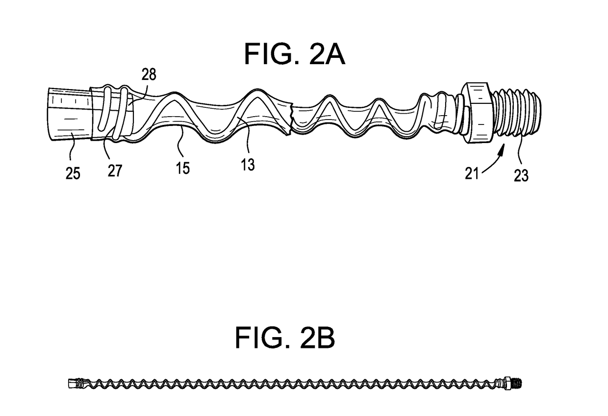
[0093]In a first embodiment, the method comprises physically expanding a tube over a helical spring and then letting the tube contract. In this embodiment, the tube member in its initial state has an inner diameter ID that is smaller than the outer diameter OD of the spring. The tube can then be physically expanded in diameter by known methods (e.g., with high-pressure air, or with heat) until it reaches a dimension where its ID is larger than the OD of the spring. In this expanded condition, the tube is passed over the spring. When the force / energy upon the tube is removed, the tube in this assembly reverts to its original dimensions, except in the locations where it touches the helical spring member. The resulting product is an auger-like assembly with peaks and valleys.

[0094]Therefore, in accordance with the present invention, there is provided a method comprising the steps of:[0095]a) applying a physical force upon a tube to expand the tube,[0096]b) passing a helical spring into...

second embodiment

[0100]In a second embodiment, the method comprises radially compressing the helical spring and then applying heat to the spring to allow its stressed areas to expand to a larger diameter. In this embodiment, the helical spring's outer diameter is reduced from its resting state (e.g., by winding the helical spring very tightly, or by pulling the helical member and thereby producing an elongated spring having a smaller outer diameter). In this reduced-diameter configuration, the radially compressed spring can be inserted into the tube member. Upon release of the mechanical force causing diameter reduction, the helical spring reverts to its original dimensions. Because the tube member possesses some flexibility, the elastic nature of the tube allows it to be deformed by the pressure of the expanding helical member upon the tube ID. Another auger-like assembly with valleys and summits is thereby produced.

[0101]Therefore, in accordance with the present invention, there is provided a meth...

third embodiment

[0107]In a third embodiment, the method comprises simultaneously applying heat and vacuum to an ordinary polymeric tube to obtain the same effect as a heat shrink. In this embodiment, the tube member is made of a material that is not heat-shrinkable, but rather is plastically deformable under heat and so over time arrives at an elastomeric state. In this embodiment, the tube member has an inner diameter ID in its initial state that is larger than the outer diameter OD of the helical spring, so that the helical member can be inserted into the tube member. Once the spring is inside the tube, a low pressure region / vacuum is created inside of the tube member, and the tube member is heated at the same time. These conditions create deformation in the wall of the tube member caused by the vacuum pulling towards the center of the tube. This reduces the diameter of the tube member, except for the locations where the helical member contacts the inside of the tube and so prevents deformation o...


PUM


Abstract

A flexible auger design for low-torque transmitting drive shafts, which allows effective tissue material transport through curved, flexible tubes and channels. A hollow auger has a hollow center, so that the helical member hugs the inner wall of the tube and material is transported along the center axis and the inner wall of the tube. The hollow flexible auger allows for transportation of material from an operative location in the patient (material removal) as well as to operative location in the patient (material delivery).

Description

CONTINUING DATA[0001]This application claims priority from U.S. provisional patent application U.S. Ser. No. 62 / 032,754, filed Aug. 4, 2014, entitled “Flexible Transport Auger”, (Thommen et al.), the specification of which is incorporated by reference in its entirety.BACKGROUND OF THE INVENTION[0002]The natural intervertebral disc contains a jelly-like nucleus pulposus surrounded by a fibrous annulus fibrosus. Under an axial load, the nucleus pulposus compresses and radially transfers that load to the annulus fibrosus. The laminated nature of the annulus fibrosus provides it with a high tensile strength and so allows it to expand radially in response to this transferred load.[0003]In a healthy intervertebral disc, cells within the nucleus pulposus produce an extracellular matrix (ECM) containing a high percentage of proteoglycans. These proteoglycans contain sulfated functional groups that retain water, thereby providing the nucleus pulposus within its cushioning qualities. These nu...

Claims


Application Information

Patent Timeline
Patent Type & Authority Patents(United States)
IPC IPC(8): A61B17/32A61B17/30A61B17/16A61B17/00
CPCA61B17/1671A61B17/30A61B17/32002A61B2017/320024A61B2017/00261A61B2017/00685
Inventor THOMMEN, DANIELRICHTER, JOERNCHEGINI, SALMANPETERSON, JOSEPHO'NEIL, MICHAEL JGREELEY, GABRIEL EMMETTDE NARDO, MATTHEW BRIANROUX, SERGE CYRILWHITNEY, ASHLEY LAURENDIVINCENZO, JOHNMARTIN, THOMAS
Owner MEDOS INT SARL
Why Eureka
Try Eureka