Devices incorporating a bi-stable ribbon spring

Inactive Publication Date: 2008-03-25
SHAW EDWARD EMIL
View PDF22 Cites 75 Cited by
  • Summary
  • Abstract
  • Description
  • Claims
  • Application Information

AI Technical Summary

Benefits of technology

[0008]The present invention utilizes the bi-stable characteristics of a snap action ribbon spring to create a self-latching, spring-loaded mechanism that greatly simplifies the design of many devices. The dual mode stability of the spring eliminates the need for complex latching mechanisms thereby simplifying the device manufacture and device reliability. The spring is stable in either a linear or coiled state that enables the simplified design of rolling, hinging and feeding mechanisms.
[0009]A map rolling and presentation device of the present invention incorporates a bi-stable snap action ribbon spring along with optional spring end caps and stiffening elements. This device of the present invention, when attached to a plan or map forces the plan or map into a convenient stable coiled or rolled shape, allowing effective transportation or storage. The user can then un-coil the ribbon spring along with attached plan or map and “snap” the spring to induce a second stable linear or planer shape. While in this planer shape, the plan or map can be reviewed without the aid of a secondary surface or devices to prevent spontaneous roll-up of the plan or map. The user can return the map or plan to the rolled state

Problems solved by technology

These additional mechanisms add complexity and cost to spring load

Method used


Image

  • Devices incorporating a bi-stable ribbon spring
  • Devices incorporating a bi-stable ribbon spring
  • Devices incorporating a bi-stable ribbon spring

Examples


example 2

[0069]A snap hinge of the present invention was constructed using the following materials and processes:

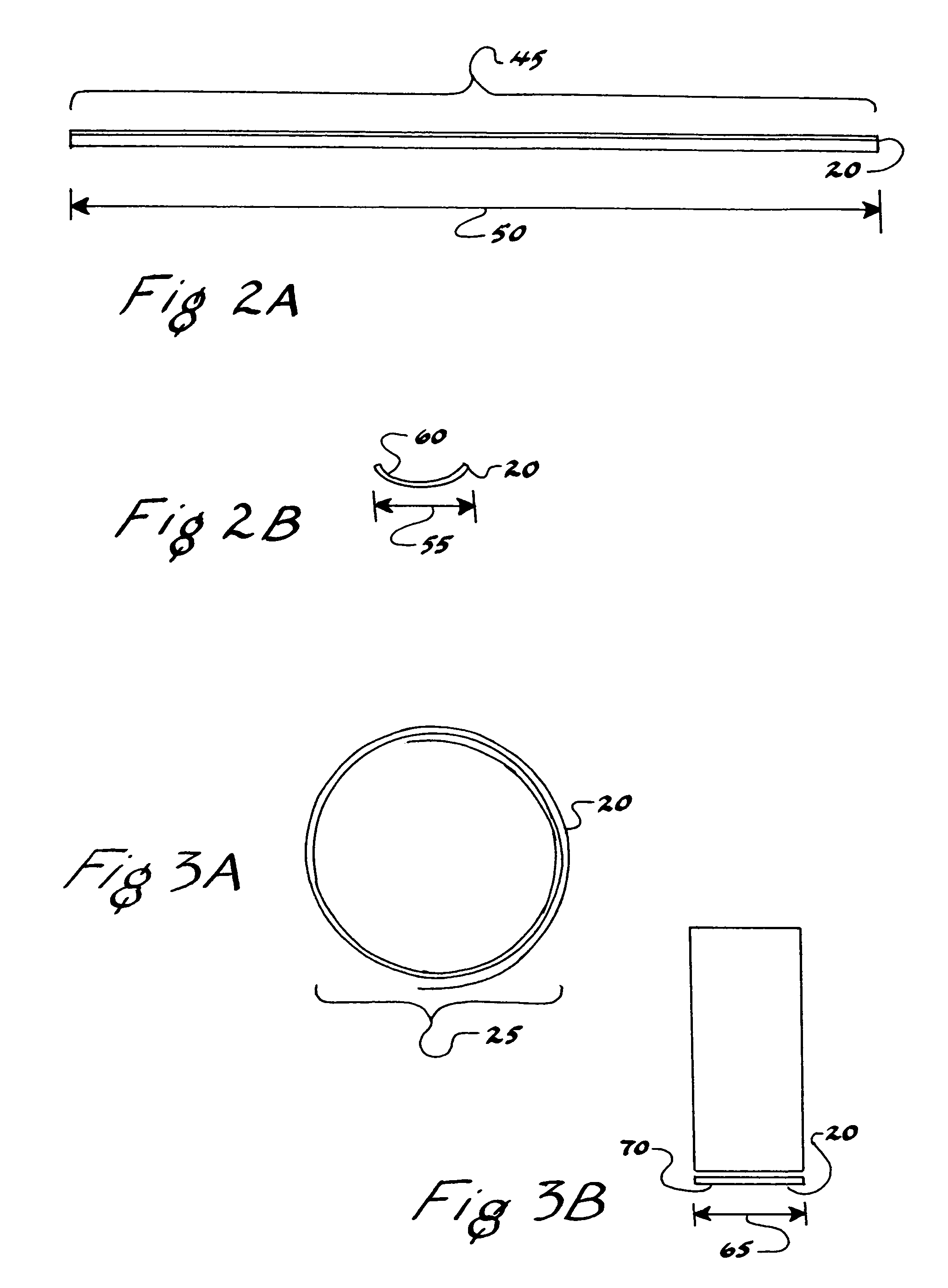
[0070]1) A hinge component was fashioned from a 12 inch length of a one inch wide tape measure tape (Lufkin® L525). At the approximate mid point along the length of the tape of the tape, a discrete length of about 1″ was drawn over a 0.19″ diameter dowel pin with the crown of the tape width being in contact with the pin. Each end of the tape was manually tensioned with the aid of pliers to about 30 lbs. during the drawing of the tape over the pin. The ends affected by the clamping were cut with heavy scissors, leaving about a 6″ total length with an integral hinging length of about 1″. The tape acted as a snap-spring only along the converted 1″ length and therefor formed a bi-stable hinging tape.

2) Each end of the bi-stable hinging tape was then attached to a 3.75″ length of 1.75″ inner diameter plastic tubing with capped ends (DAP® caulking tubes). The spring ends were attached t...

example 3

[0071]A can dispenser of the present invention was constructed using the following materials and processes:

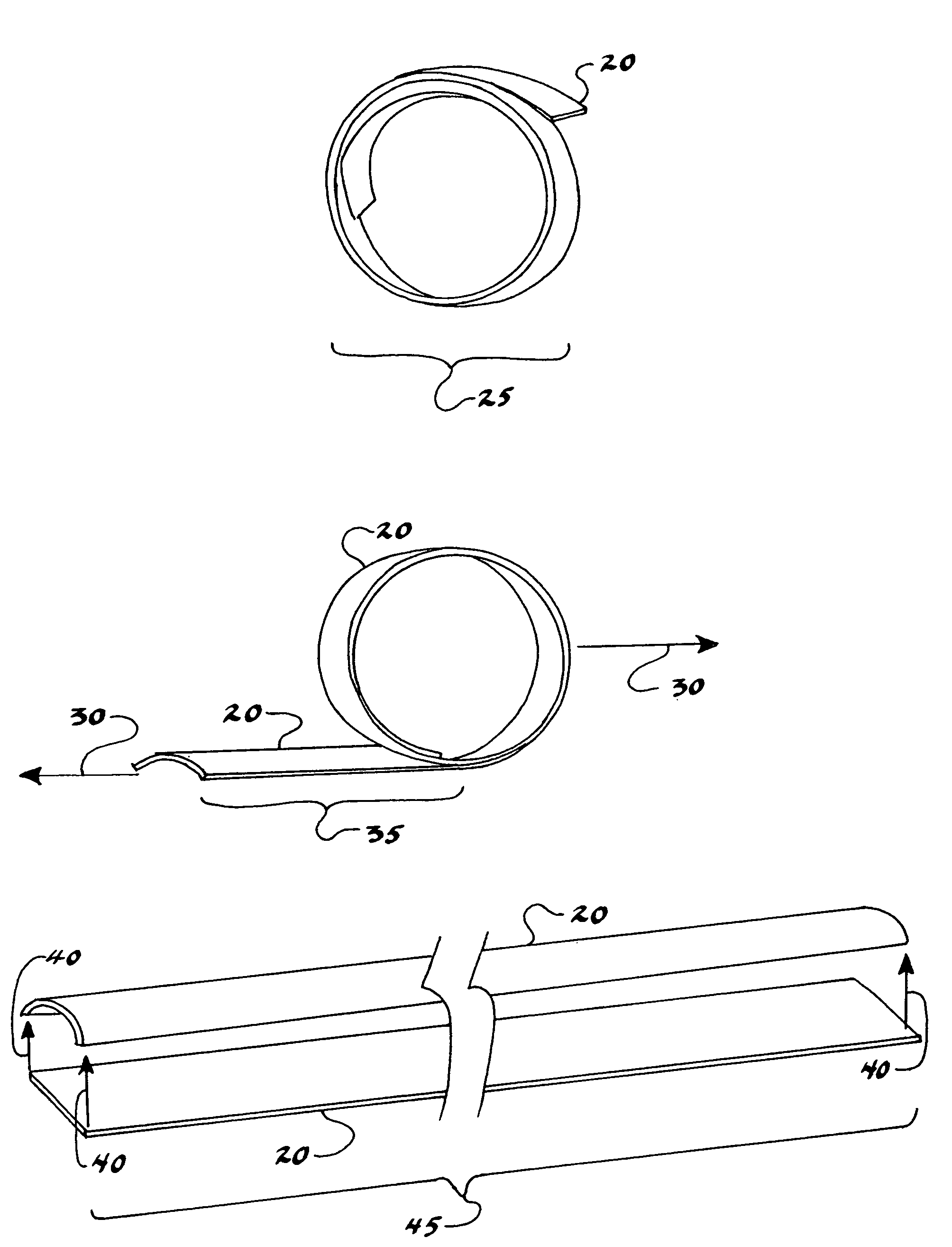
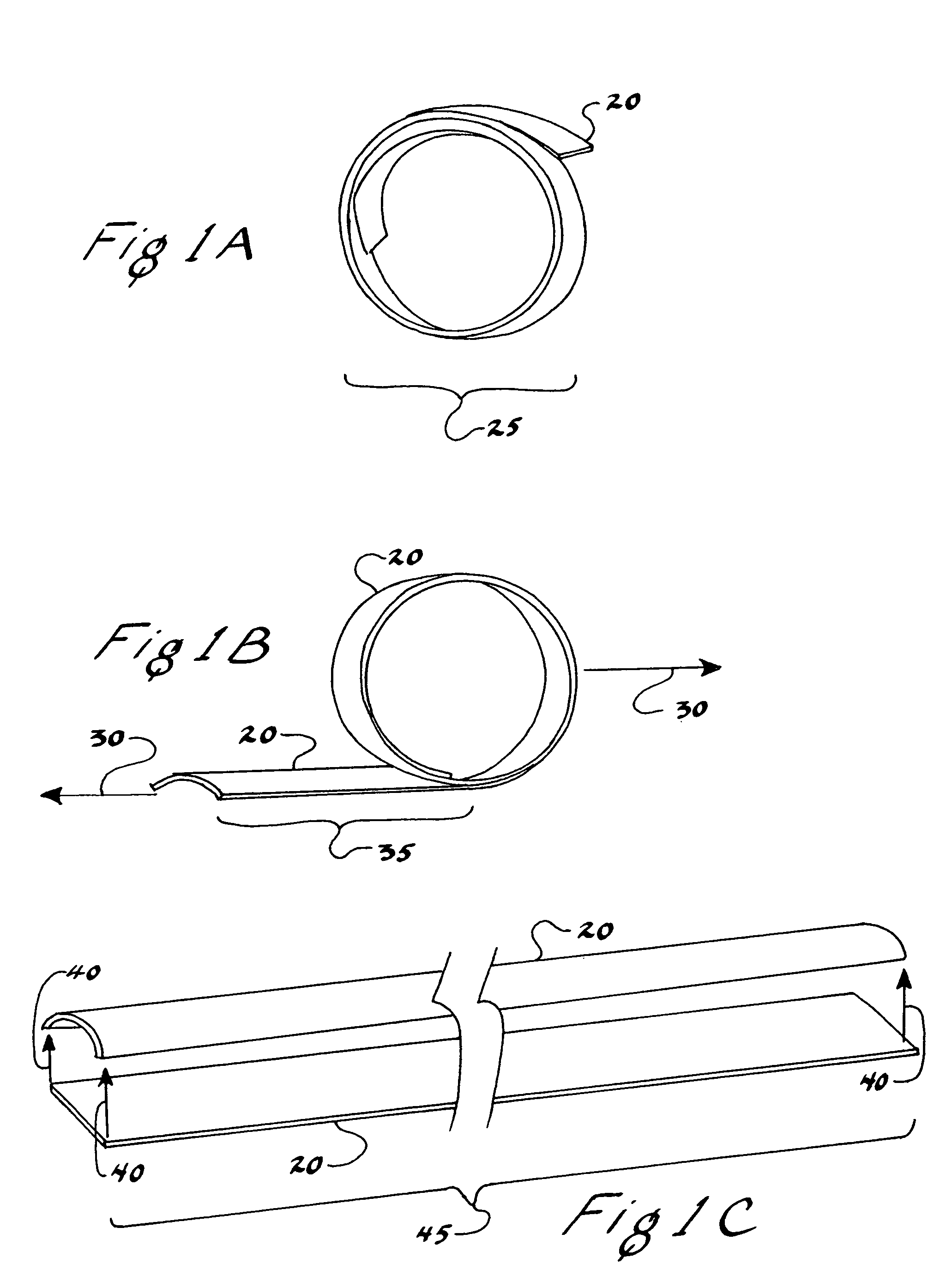
[0072]1) Two identical snap-spring components were fashioned from a 36 inch lengths of one inch wide tape measure tape (Lufkin® L525). The normally straight tape was converted into a coiled spring over about 30″ of its length by drawing it over a small 0.125″ diameter dowel pin with the crown of the tape width being in contact with the pin. The remaining 6″ of tape was converted into a snap-spring by drawing it over a larger 0.19″ diameter dowel pin with the crown of the tape width being in contact with the pin. Each end of the tape was manually tensioned with the aid of pliers to about 30 lbs. during the drawing of the tape. The ends affected by the clamping were cut with heavy scissors, leaving about 5″ of snap-spring length and about 21″ of coiled spring length in each of the about 26″ long tape segments.

2) Acrylic tubing with an inside diameter slightly larger than the outs...


PUM


Abstract

A bi-stable snap action ribbon spring incorporated into self-latching, spring-loaded mechanisms. The dual mode stability of the spring eliminates the need for complex latching mechanisms thereby simplifying the device manufacture and device reliability. The spring is stable in either a linear or coiled state enabling the simplified design of rolling, hinging and feeding mechanisms. A plan or map rolling and presentation device incorporates a bi-stable snap action ribbon spring along with optional spring end caps and stiffening elements. The plan or map is driven to a stable coiled or stable rolled shape by the influence of the snap action spring. Application of the snap spring properties to a discreet length of a longer ribbon can create a hybrid bi-stable hinge mechanism. A convenient storage container utilizes the bi-stable characteristics of a snap action ribbon spring to create a container having a self-closing and captured lid. A can or drum feeder incorporates the bi-stable characteristics of a snap action ribbon spring to provide a device that reliably stores and presents cans such as soda cans.

Description

FIELD OF THE INVENTION[0001]The present invention relates to devices that incorporate a bi-stable ribbon spring and in particular rolled article storage devices, hinging devices and can or drum feed devices utilizing a bi-stable ribbon spring.BACKGROUND OF THE INVENTION[0002]In the world of mechanical devices there are many examples of mechanical action driven by a spring force. Examples of such mechanical systems include map or plan rollers, window or opening covers, hinged containers and can or drum feeding mechanisms.[0003]In some of these applications it is desirable to provide a latching mechanism to maintain the spring in its pre-loaded state until such a time, as the force of action is required. Traditionally, the latching mechanism has been in the form of a secondary mechanical device such as a pawl, latch or catch. These additional mechanisms add complexity and cost to spring loaded systems and may ultimately affect the reliability of the system.[0004]A bi-stable ribbon spr...

Claims


Application Information

Patent Timeline
IPC IPC(8): G09F15/00
CPCF16F1/025G09F15/00
Inventor SHAW, EDWARD EMIL
Owner SHAW EDWARD EMIL
Why Eureka
Try Eureka