Boot binding coupling for snow boards

Inactive Publication Date: 2000-08-01
VETTER DENNIS A +1
View PDF11 Cites 28 Cited by
  • Summary
  • Abstract
  • Description
  • Claims
  • Application Information

AI Technical Summary

Benefits of technology

The present invention provides a snowboard coupling for use between the snowboard and the user boot binding and a quick release from the standing position. The coupling allows the user to reengage the boot binding to the board as the user dismounts from the ski lift chair by standing on the coupling followed by a short twisting motion that exploits the strength of the leg muscles.
To easily locate the shoe into the arcuate large opening, a plurality of guide pins are provided on a circular arc on the boot binding plate outside of the lock pins and outside the radius of the turntable, extending slightly farther from the plate than do the lock pins. In use, the guide pins first orient the boot binding plate over the turntable ring. Slight movement then quickly locates the lock pin shoes into the turntable slots. The guide pins also serve as improved traction devices when the user is pushing with the disengaged boot binding to move toward a chair lift.

Problems solved by technology

However, snowboarding differs from skiing in that both user boots attach to a single snowboard, and the user does not employ poles.
Thus, the snowboarder often finds himself stopped soon after dismounting from the ski lift chair to remount his free boot, often endangering himself and others, or he may have fallen for lack of adequate control.
Generally, one boot had to be unstrapped from a board, an inconvenient and cumbersome task, as best.
Although routine for traditional skiers, this normally simple task became a challenge without poles to assist, using only the disengaged boot pushing against the snow and ice with limited traction.
This is usually very difficult and perhaps dangerous.
In practice, it is found that the coupling does not operate quickly enough to reengage upon dismount from the lift chair during the dismount action.
It is also found that when ice gathers in the binding, the boot may not mount at all until ice is cleared.
Thus, the problem remains to have a binding that is not only easily released but that reliably and quickly reengages the boot onto the board, even in the presence of ice and snow.

Method used


Image

  • Boot binding coupling for snow boards
  • Boot binding coupling for snow boards
  • Boot binding coupling for snow boards

Examples


Embodiment Construction

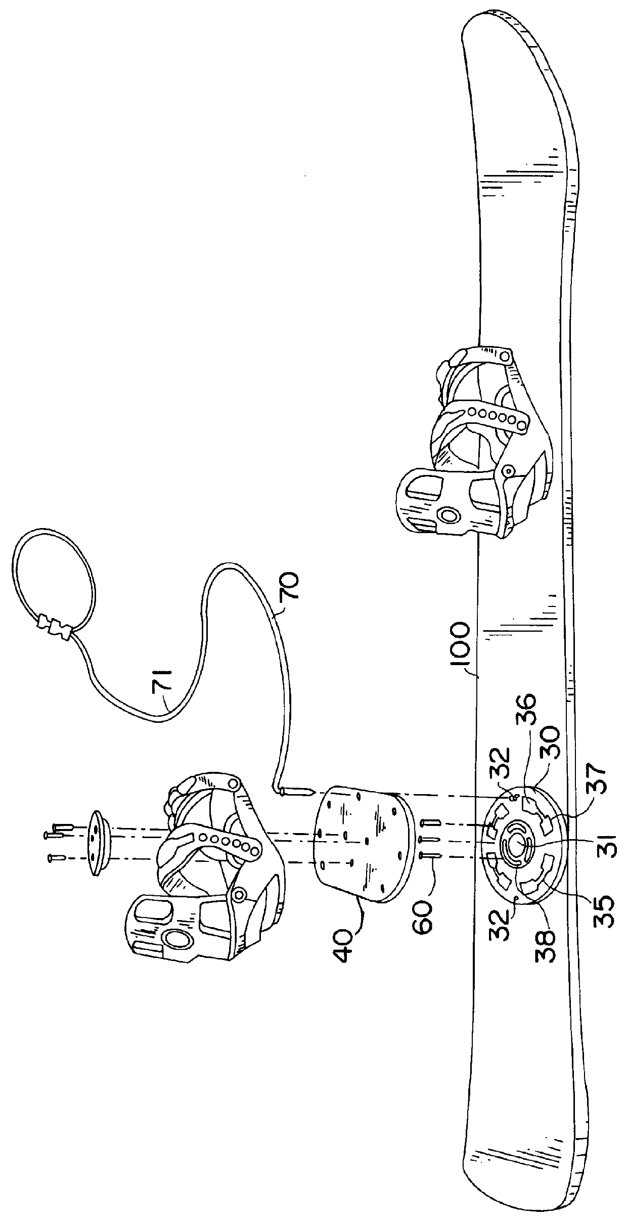
Referring to the figures, the present invention comprises a spacer plate 10, mounting plate 20, a circular turntable ring 30 with a concentric center hole 31, a plurality of latch pin holes 32 , a boot binding plate 40 , and a release latch pin unit 50.

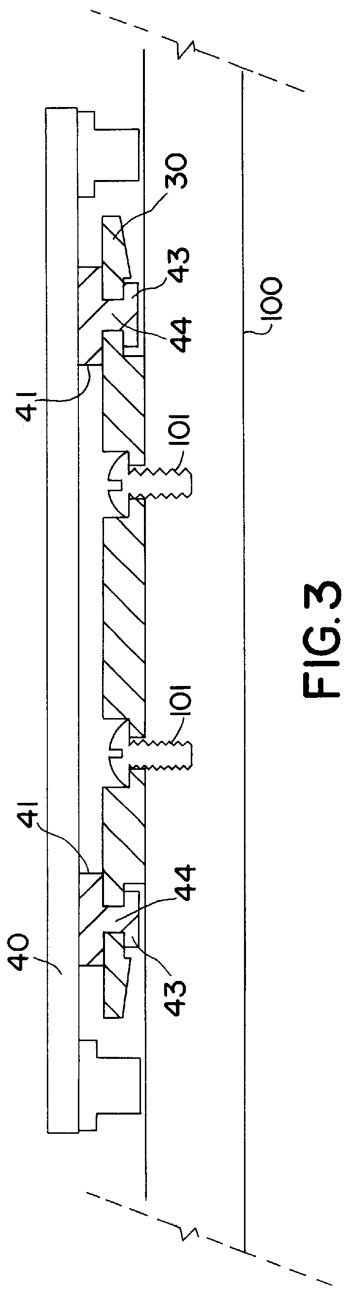
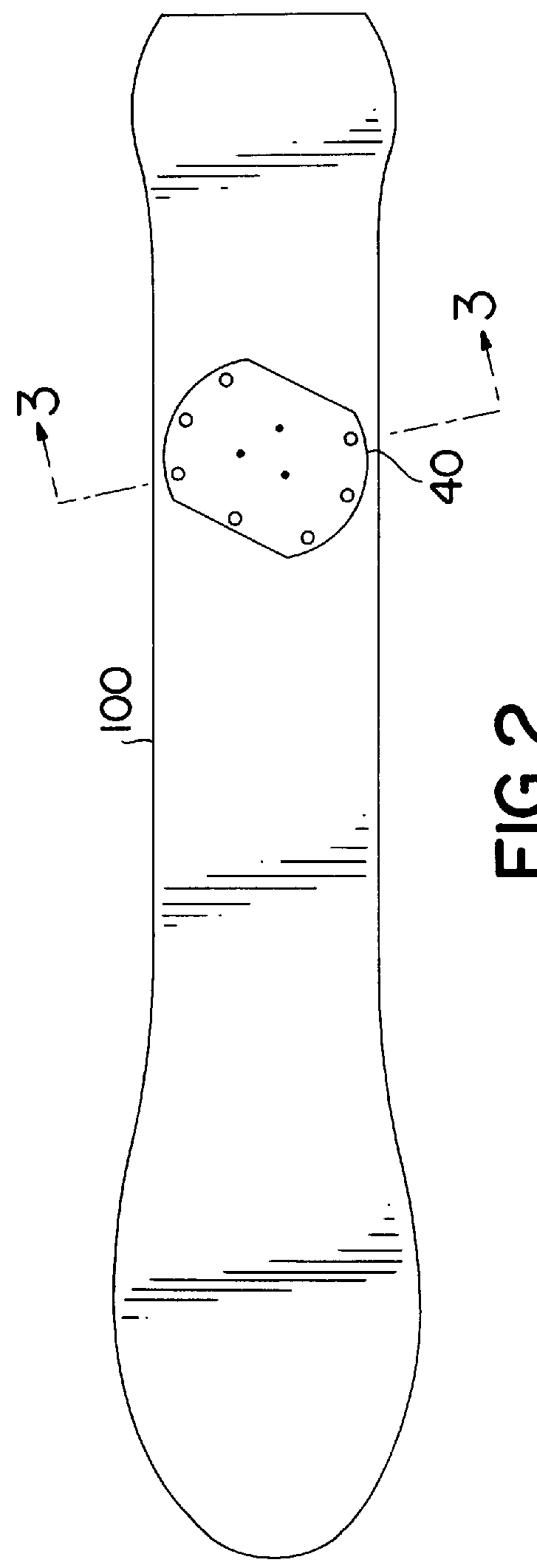
The spacer plate 10 comprises a set of mounting holes 11 matching a pattern of threaded screw holes 101 in a snowboard 100 against which this plate is secured.

The mounting plate 20 comprises a set of mounting holes 21 matching those of the spacer plate 10. About the circumference of this spacer plate 20 is an annular raceway 21 formed by a circumferential flat 22 on the plate edge 23.

The turntable ring 30 comprises an inner annular journal surface 33 defining its inner center hole 31 sized to fit into the raceway of the mounting plate 20. With mounting plate 20 concentrically placed over the turntable ring 30 with its mounting holes 24 in alignment with the spacer plate mounting holes 11, the turntable ring 30 is secured to the snowbo...


PUM


Abstract

A coupling for releasably mounting a boot with boot binding to a turntable which is adjustably secured to a snowboard. The boot binding includes a plurality of extending lock pins each with a shoe releasably locking into arcuate slots in the turntable. The boot binding is quickly directed to the coupling with a set of guide pins protruding from the boot binding, which pods also serve as improved traction devices when the boot binding is disengaged from the turntable. Also extending from the boot binding plate is a latch pin held under spring bias which when aligned in a hold position, fits into one of several latch pin holes in the turntable. To release the plates from hold position, the latch pin is pulled from the latch pin hole by a flexible hand extension release device hand operated from a standing position and the plates are rotated to disengage the shoes from the arcuate slots.

Description

TECHNICAL FIELDThis invention relates to snow boards, and more specifically, to a coupling useful for releasably connecting a user boot binding to a snowboard, operated via a flexible hand extension release device.BACKGROUND OF THE INVENTIONIt has become well-known in recent years to use snowboards on ski slopes as another form of winter recreation similar to skiing- Snowboards are commercially available, for example, from Burton Snowboards of Manchester, Center, Vt.A snowboard rider uses a boot designed especially to the requirements of snowboarding. As with skiing, it is required to secure the boot to the snowboard with a binding. However, snowboarding differs from skiing in that both user boots attach to a single snowboard, and the user does not employ poles. Also unlike skiing, the boot bindings are mounted to the snowboard with screws into a pattern of screw holes, possible threaded inserts in the snowboard. This pattern of screw holes or inserts typically allows adjustment in ...

Claims


Application Information

Patent Timeline
IPC IPC(8): A63C9/08A63C10/14A63C10/18
CPCA63C10/14A63C10/18
Inventor VETTER, DENNIS A.EATON, ERIC L.
Owner VETTER DENNIS A
Why Eureka
Try Eureka