
Snowmobile suspension

a technology for suspensions and snowmobiles, applied in suspensions, snowmobiles, vehicle components, etc., can solve the problems of less discomfort for the operator of snowmobiles, deflections, and displacements

Inactive Publication Date: 2003-05-27
BOMBARDIER RECREATIONAL PROD INC +1
View PDF27 Cites 40 Cited by
  • Summary
  • Abstract
  • Description
  • Claims
  • Application Information

AI Technical Summary

Benefits of technology

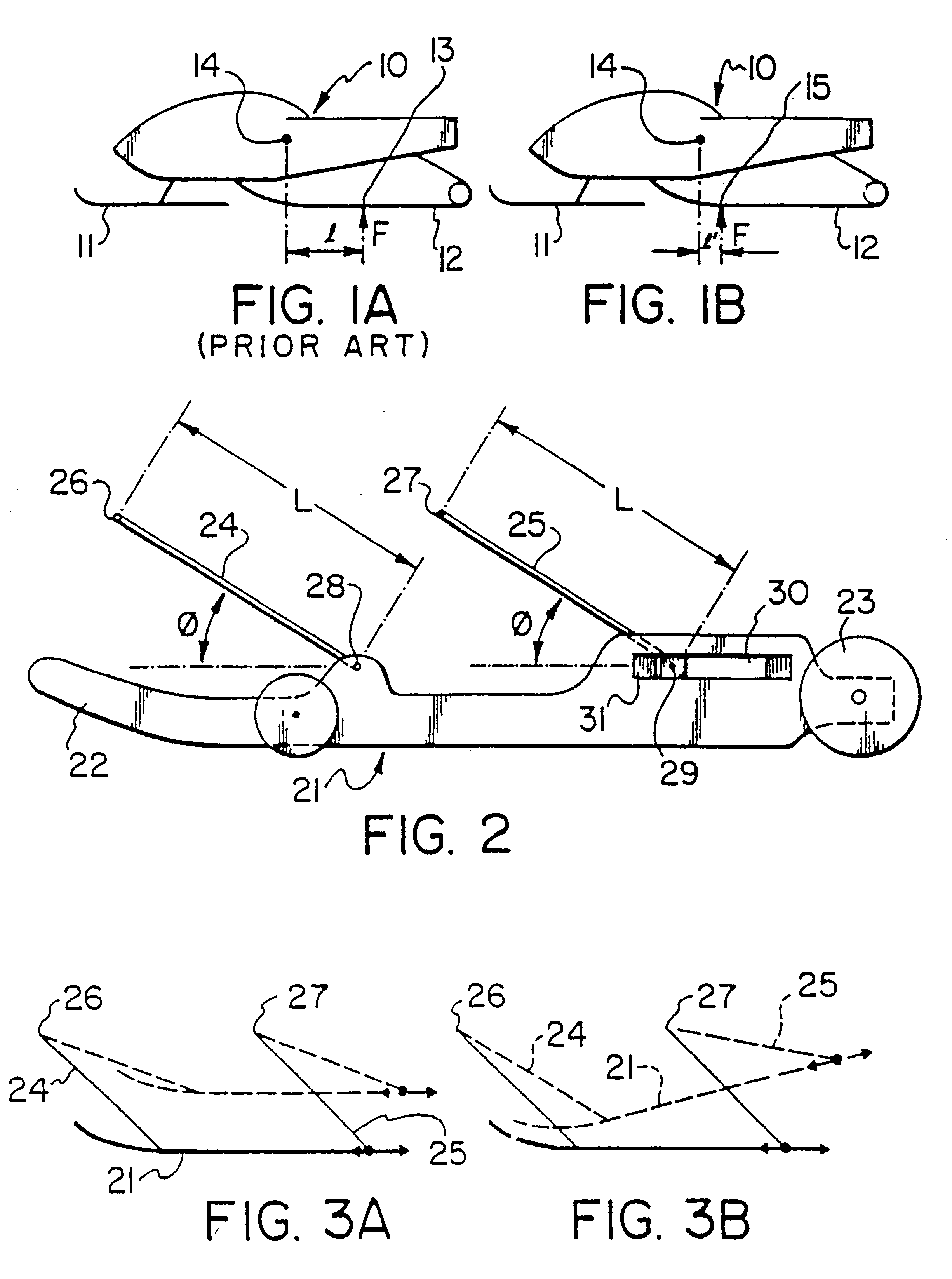
With such an arrangement it is ensured that the loading imposed upon the track suspension by undulations in the terrain over which the snowmobile travels acts more on the front part of the track suspension than on its rear part, and thus effectively moves the average point of application of the vertical forces forwardly closer to the center of gravity of the vehicle, and accordingly reduces the resulted couple that produces the undesired angular acceleration.

Problems solved by technology

Irregularities in the terrain travelled by the snowmobile produce displacements and deflections of the snowmobile front suspension that supports the vehicle on the skis, and of the rear suspension.
Depending upon their magnitude, frequency, and strength, these deflections cause more or less discomfort to the operator of the snowmobile.

Method used


Image

  • Snowmobile suspension
  • Snowmobile suspension
  • Snowmobile suspension

Examples


Embodiment Construction

Referring to FIGS. 1A and 1B, a snowmobile chassis 10 is schematically illustrated as being supported in the usual manner upon a pair of steerable skis 11 at its forward end and upon the ground engaging run of a driven track belt 12 at its rearward end. FIG. 1A represents the situation that exists with a track suspension of prior art construction wherein the loading point 13 where ground induced forces absorbed by the track suspension are applied to the snowmobile chassis is positioned rearwardly of the snowmobiles center of gravity 14 by a distance l.

It will be understood that the angular acceleration .alpha. applied to the snowmobile when the track encounters an undulation that generates a force F at the loading point 13 will be directly proportional to the couple T and inversely proportional to the moment of inertia I of the snowmobile about its center of gravity.

In other words

The couple T is the product of the force F and the distance l, so that accordingly the angular accelerat...


PUM


Abstract

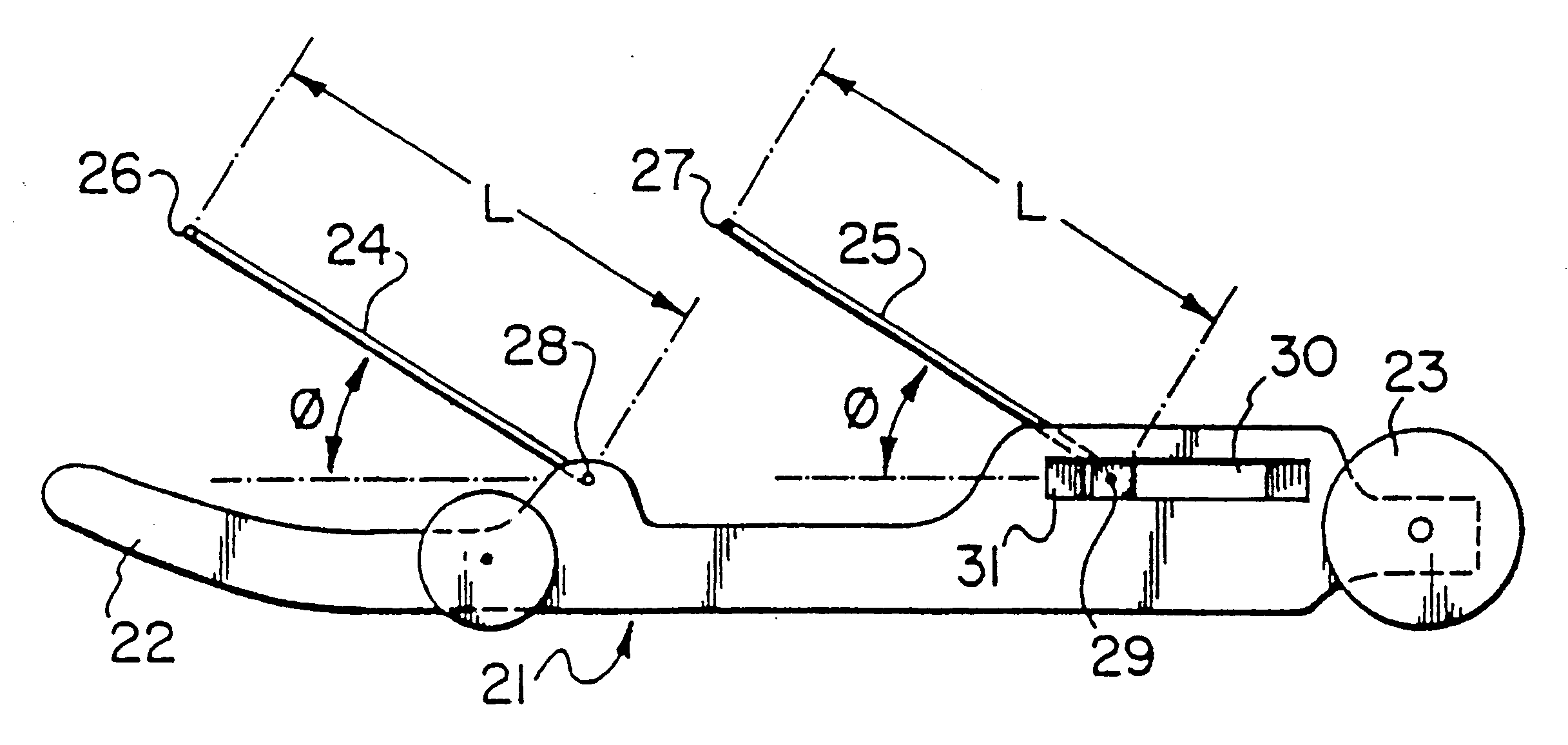
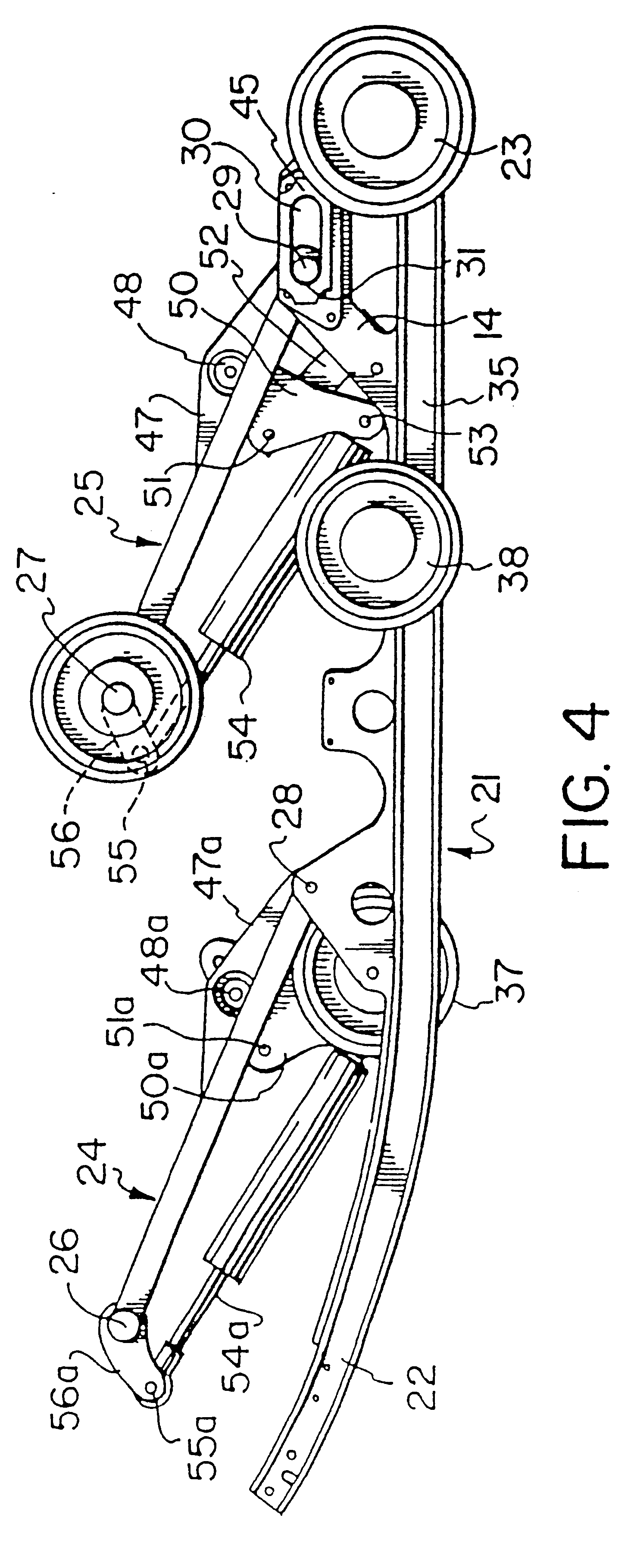
In a snowmobile track suspension, the slide frame is supported upon downwardly and rearwardly angled front and rear suspension arm assemblies. The suspension arm assemblies are of similar construction, length, and orientation, having upper ends connected to fixed pivots in the snowmobile chassis and lower ends pivoted to the slide frame. The lower end of the rear suspension arm assembly has a pivot mount that is movable longitudinally of the slide frame. Movement in the forwards direction being blocked by an abutment which ensures that during suspension travel the front end of the slide frame cannot move higher than the rear end thereof.

Description

BACKGROUND OF THE INVENTIONa) Field of the InventionThis invention relates to a new or improved snowmobile track belt suspension.b) Description of the Prior ArtSnowmobile track belt suspensions often employ a slide frame pressed into contact with the upper side of the ground engaging run of the track belt loop by spring arrangements associated with suspension arm assemblies by which the slide frame is connected to the snowmobile chassis. Typically, two angulated arm assemblies are employed to connect the slide frame to the snowmobile chassis, and these arm assemblies are movable independently of one another to permit the slide frame to accommodate itself to static and dynamic forces arising in operation.Irregularities in the terrain travelled by the snowmobile produce displacements and deflections of the snowmobile front suspension that supports the vehicle on the skis, and of the rear suspension. Depending upon their magnitude, frequency, and strength, these deflections cause more ...

Claims


Application Information

Patent Timeline
IPC IPC(8): B62D55/104B62D55/116
CPCB60G2200/17B60G2204/128B60G2204/129B60G2204/421B60G2204/422B60G2300/322B62D55/116
Inventor MALLETTE, BERTRANDKARPIK, GERARD J.
Owner BOMBARDIER RECREATIONAL PROD INC
Learn More