Apparatus and method for rotating the display orientation of a captured image

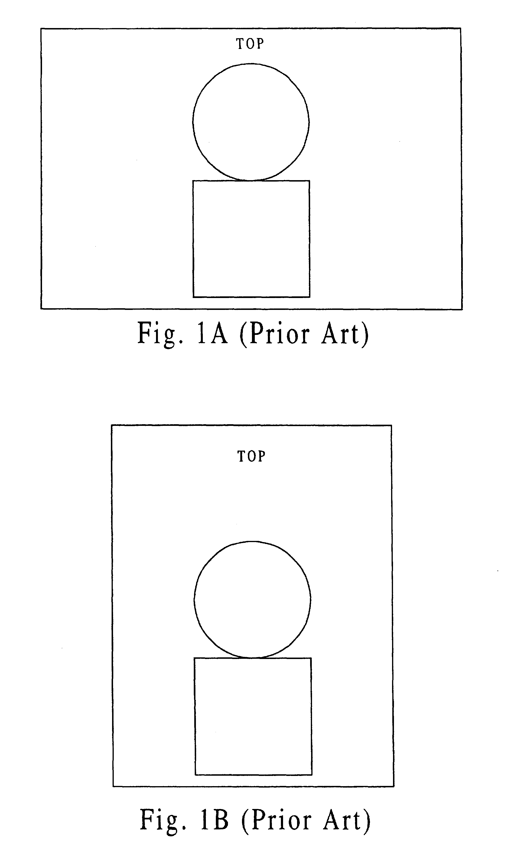
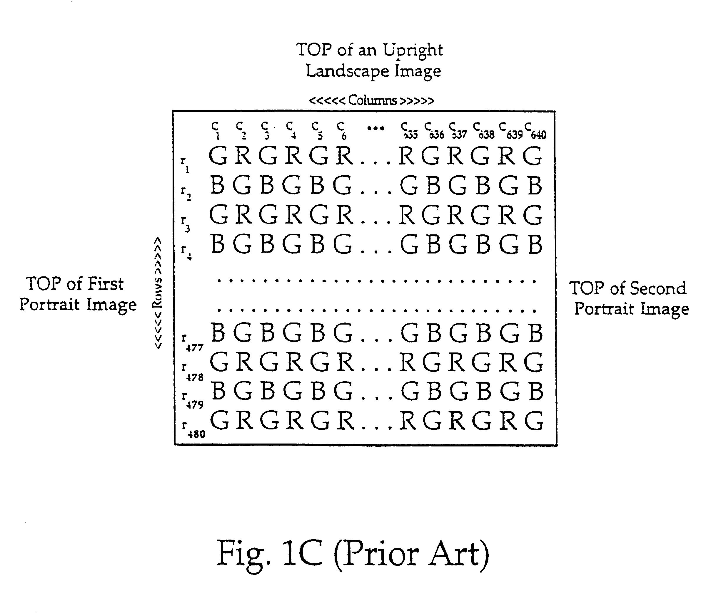
a technology of an image and a rotating device, applied in the field of apparatus and methods for orienting images, can solve the problems of unnatural orientation of portrait images on the image display b>100/b>, the disadvantage of two blocks of memory for rotating a stored image, and the problem of digitized images from conventional film cameras

Inactive Publication Date: 2005-11-29
APPLE INC
View PDF29 Cites 149 Cited by
  • Summary
  • Abstract
  • Description
  • Claims
  • Application Information

AI Technical Summary

Problems solved by technology

This “sideways” orientation for portrait images on the image display 100 is unacceptable and unnatural.
It should be noted that this problem also exists for digitized images from conventional film cameras.
Traditional rotation methods also have the disadvantage of requiring two blocks of memory to rotate a stored image.

Method used


Image

  • Apparatus and method for rotating the display orientation of a captured image
  • Apparatus and method for rotating the display orientation of a captured image
  • Apparatus and method for rotating the display orientation of a captured image

Examples


Embodiment Construction

[0029]The present invention is an apparatus and method for rotating the display orientation of a captured image.

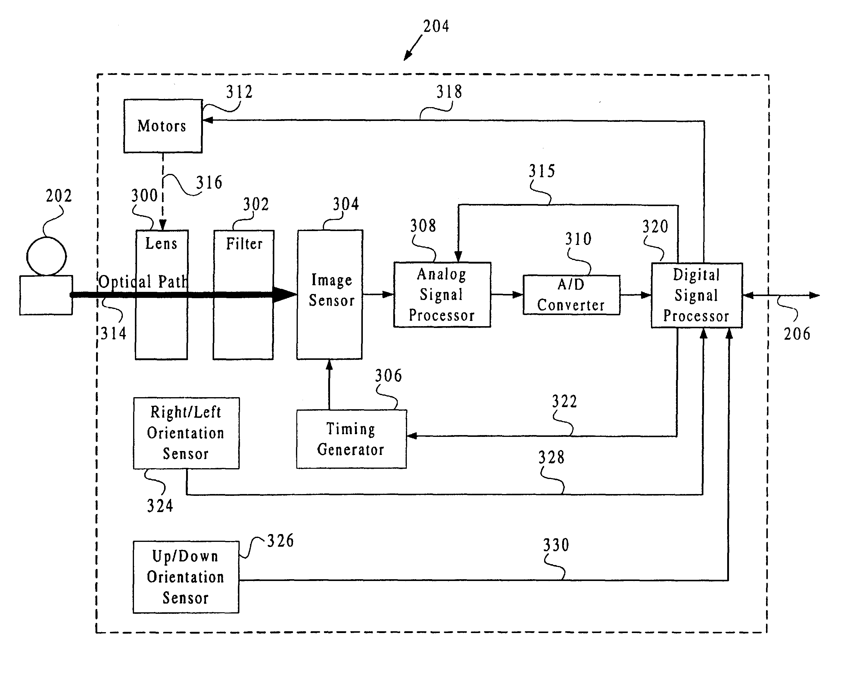
[0030]Referring now to FIG. 2, a block diagram is shown illustrating a camera 200 for rotating a display orientation of a captured image. In the preferred embodiment, the camera 200 is a digital camera, such as a QuickTake 150, by Apple Computer of Cupertino, Calif. The camera 200 preferably comprises an imaging subsystem 204, a bus 206 and a processing and storage subsystem 208. Reflected light from an object 202 is conventionally captured by the imaging subsystem 204 via a button press or some other action. The captured image data is transferred over the bus 206 to the processing and storage subsystem 208, which stores the data in internal memory. The bus 206 also passes various status and control signals between the imaging subsystem 204 and the processing and storage subsystem 208, as will be further discussed below.

[0031]Referring now to FIG. 3A, a block diagram is sh...


PUM


Abstract

The apparatus of the present invention preferably comprises an image sensor, an orientation sensor, a memory and a processing unit. The image sensor is used for generating captured image data. The orientation sensor is coupled to the image sensor, and is used for generating signals relating to the position of the image sensor. The memory, has an auto-rotate unit comprising program instructions for transforming the captured image data into rotated image data in response to the orientation sensor signals. The processing unit, executes program instructions stored in the memory, and is coupled to the image sensor, the orientation sensor and the memory. The method of the present invention preferably comprises the steps of: generating image data representative of an object with an image sensor; identifying an orientation of the image sensor relative to the object during the generating step; and selectively transferring the image data to an image processing unit in response to the identifying step.

Description

[0001]This application relates to co-pending U.S. patent application Ser. No. 08 / 355,031, entitled A System and Method For Generating a Contrast Overlay as a Focus Assist for An Imaging Device, filed on Dec. 13, 1994, by inventor Eric C. Anderson; and U.S. patent application Ser. No. 08 / 384,012, entitled Apparatus and Method for Camera Image and Orientation Capture, filed on Feb. 6, 1995, by inventor Scott Fullam. The subject matter of the two applications described above is hereby incorporated by reference. These related applications are commonly assigned to Apple Computer, Inc.BACKGROUND OF THE INVENTION[0002]1. Field of the Invention[0003]The present invention relates generally to an apparatus and method for orienting an image. More particularly, the present invention is an apparatus and method for rotating a captured image to an orientation corresponding to an imaging subsystem's orientation at the time in which the image was captured.[0004]2. Description of the Background Art[0...

Claims


Application Information

Patent Timeline
Patent Type & Authority Patents(United States)
IPC IPC(8): H04N5/232H04N5/262H04N5/367H04N5/369H04N9/04
CPCH04N5/2628H04N2101/00H04N2201/0084H04N23/63
Inventor ANDERSON, ERIC C.
Owner APPLE INC
Why Eureka
Try Eureka