Acoustic wave imaging apparatus and method

a wave imaging and wave wave technology, applied in the field of acoustic wave imaging systems, can solve the problems of affecting the accuracy of the image, the disadvantage of one dimensional systems, and the cost of one dimensional systems, and achieve the effect of low cost and potentially portabl

Inactive Publication Date: 2008-08-12
BATES KENNETH N
View PDF13 Cites 5 Cited by
  • Summary
  • Abstract
  • Description
  • Claims
  • Application Information

AI Technical Summary

Benefits of technology

[0014]Amongst other aspects, the present invention discloses a manner of using coded signals to achieve desired delays in 1-D, 2-D and annular array imaging systems. For 1-D imaging array systems, a manner of making and practicing linear, curved linear and sector scanning arrays that are low cost and potentially portable is presented. This teaching also applies to annular arrays. For 2-D array imaging systems, a manner of making and practicing these systems for rapid 3-D volume images and / or real time, arbitrary scan plane, 2-D sector, planar, or curved planar images is presented. In addition, the 2-D array taught herein allows for the implementation of multi-dimensional aberration correction which may allow ultrasonic images to approach the image acuity of MRI and X-ray CAT imaging systems, and to do so at a fraction of the cost of these imaging modalities.

Problems solved by technology

Present one dimensional systems are disadvantageous due to (1) the manner in which they are constructed and (2) inherent limitations in their scanning capabilities.
With respect to the manner in which they are constructed, one disadvantage is that the use of delay elements, and related electronics adds considerably to the cost of one dimensional systems.
With respect to inherent limitations, one dimensional scanning systems are disadvantageous in that they only provide two dimensional images.
A problem with applying current 1-D technology to 2-D array imaging is that a vast number of electrical connections and processing electronics are required to serve an array of practical size.
As a result of the disadvantageous aspects of providing large numbers of processing channels, current research efforts are directed towards achieving high performance with fewer array elements.
Due to reduced aperture, 1.5-D arrays may not offer the increase in elevation resolution that will justify their added expense and complexity.
Furthermore, research has shown that the use of aberration correction with 1.5-D arrays may not improve the image quality over that obtained using correction with a 1-D array.
This approach, however, has lead to significantly higher sidelobes in the beam profile of the system, compared to sidelobes in a beam profile for a full 2-D array.
Thus, these systems are not suitable for such common uses as medical diagnostic imaging and the like which requires low and extremely low level sidelobes.
They produce only a single ray, and while they perform dynamic focusing, they do not provide sector scanning.

Method used


Image

  • Acoustic wave imaging apparatus and method
  • Acoustic wave imaging apparatus and method
  • Acoustic wave imaging apparatus and method

Examples


Embodiment Construction

taken together with the drawings.

BRIEF DESCRIPTION OF THE DRAWINGS

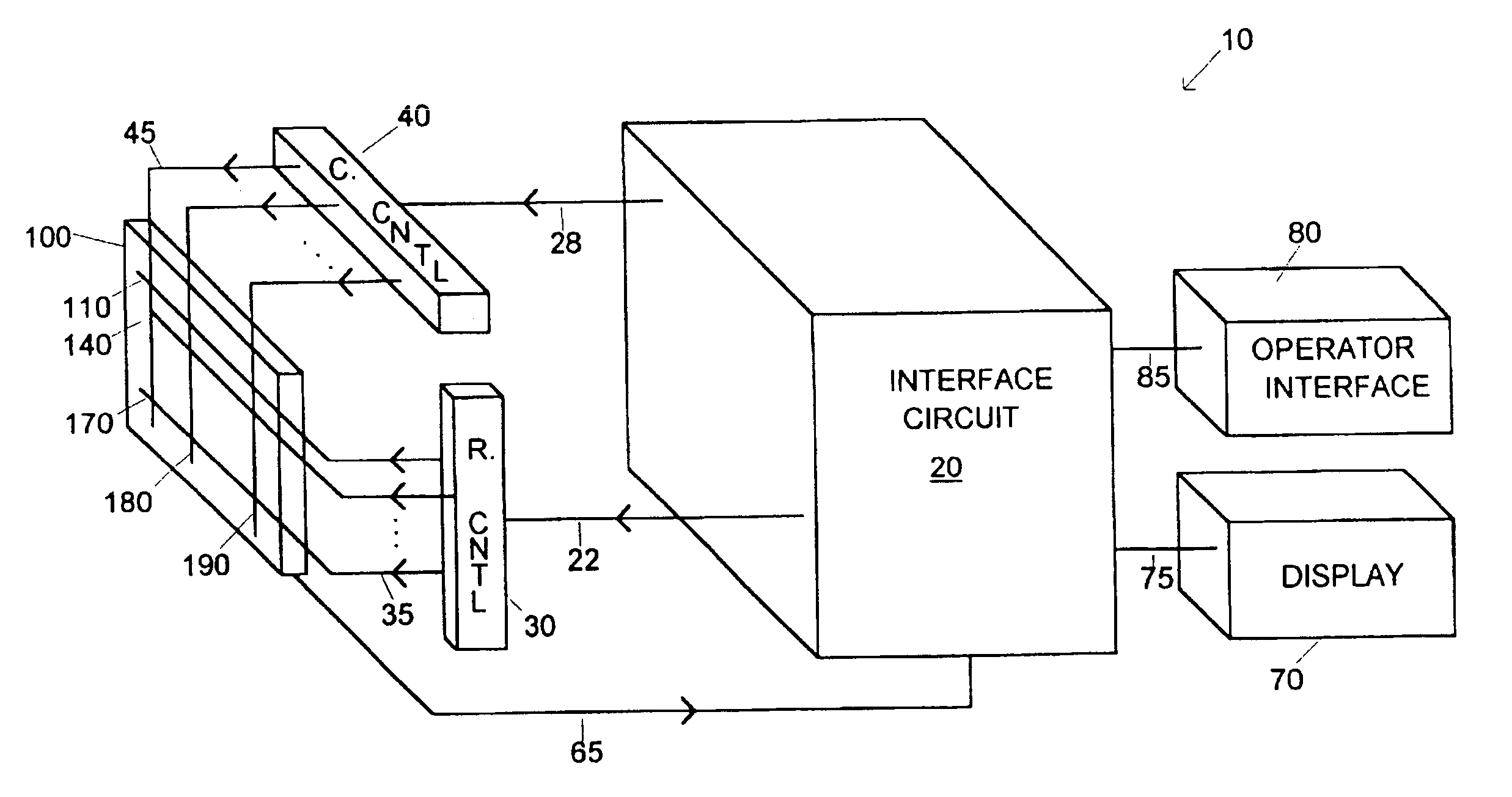
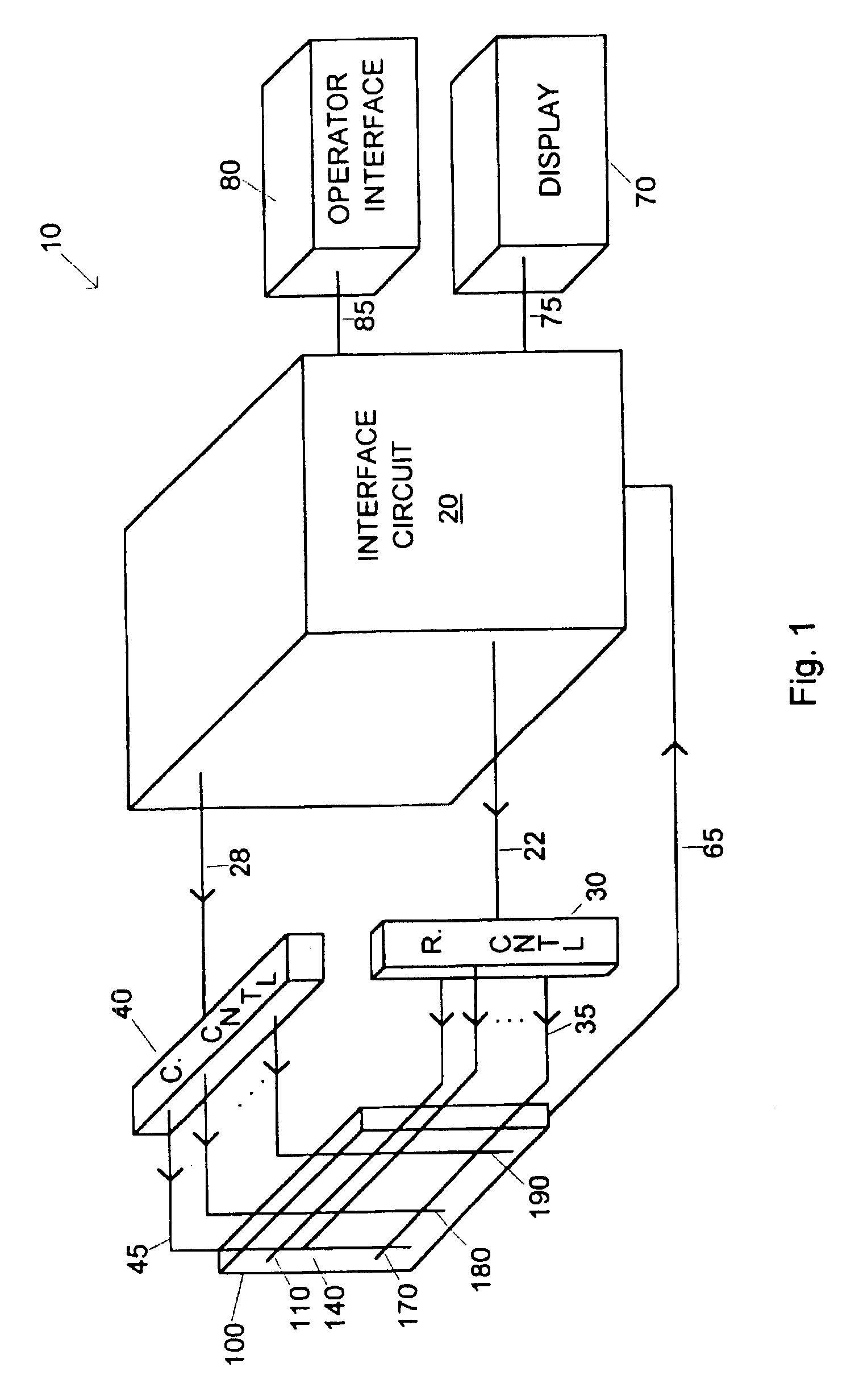
[0022]FIG. 1 is a perspective view of an acoustic wave imaging system in accordance with the present invention.

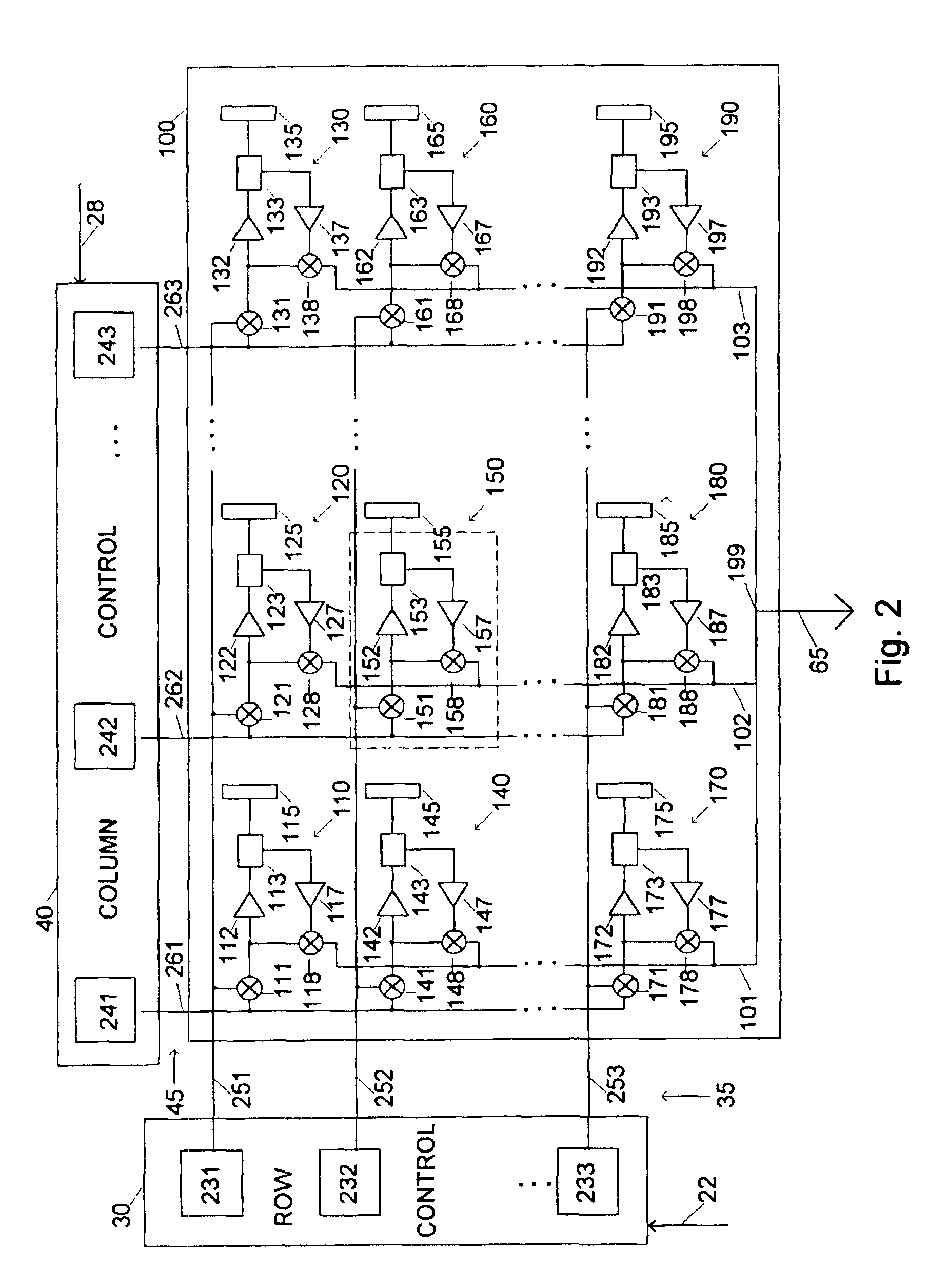
[0023]FIG. 2 is a schematic / block diagram of an acoustic transducer array and control circuits therefor in accordance with the present invention.

[0024]FIG. 3 is a block diagram of interface circuitry for an acoustic wave imaging system in accordance with the present invention.

[0025]FIG. 4 is a diagram of a chirp signal.

[0026]FIG. 5 is a diagram of planar scanning in accordance with the present invention.

[0027]FIGS. 6a-6b are diagrams of curved planar arrays in accordance with the present invention.

[0028]FIG. 7 is a schematic diagram of two cells of FIG. 2 with phase adjustment in accordance with the present invention.

[0029]FIG. 8 is a diagram illustrating aspects of discrete dynamic focusing in accordance with the present invention.

[0030]FIG. 9 is a range point versus frequency band diagram in accordance with...


PUM

PropertyMeasurementUnit
power consumptionaaaaaaaaaa
acoustic lengthaaaaaaaaaa

Abstract

An acoustic imaging apparatus and method that achieves desired delays with coded signals. Linear, curved linear and sector scanning is provided in 1-D arrays and planar, curved planar and sector scanning is provided in 2-D arrays. Composite and non-linear implementations are presented. Dynamic and discrete dynamic focusing is disclosed for the relevant arrays. The 2-D array makes possible 3-D imaging.

Description

FIELD OF THE INVENTION[0001]The present invention relates to acoustic wave imaging systems.BACKGROUND OF THE INVENTION[0002]Conventional acoustic wave imaging systems use a one dimensional (1-D) array of electro-acoustic transducers, for example, a 1×100 array, and have been configured to achieve linear, curved linear and sector scanning. Coherence in the transmission and receipt of acoustic signals is achieved by the utilization of delay devices in the signal processing channels. Present one dimensional systems are disadvantageous due to (1) the manner in which they are constructed and (2) inherent limitations in their scanning capabilities. With respect to the manner in which they are constructed, one disadvantage is that the use of delay elements, and related electronics adds considerably to the cost of one dimensional systems. With respect to inherent limitations, one dimensional scanning systems are disadvantageous in that they only provide two dimensional images.[0003]To incr...

Claims


Application Information

Patent Timeline
Patent Type & Authority Patents(United States)
IPC IPC(8): G03B42/06G01N29/00G01S7/52G01S15/89G10K11/34
CPCG01N2291/02491G01S7/52049G01S15/8915G01S15/8954G01S15/8959G10K11/341
Inventor BATES, KENNETH N.
Owner BATES KENNETH N
Why Eureka
Try Eureka