Method and apparatus for pluggable fiber optic modules

a fiber optic module and plug-in technology, applied in the field of fiber optic modules, can solve the problems of increasing the cost affecting the operation of fiber optic transceivers, and requiring additional components for using separate optical elements

Inactive Publication Date: 2010-02-23
LUMENTUM OPERATIONS LLC
View PDF174 Cites 236 Cited by
  • Summary
  • Abstract
  • Description
  • Claims
  • Application Information

AI Technical Summary

Problems solved by technology

Additionally, electromagnetic interference (EMI) is of concern due to the high frequency of operation of the fiber optic modules.
Using separate optical elements requires additional components and increases the costs of fiber optic transceivers.
Previously, the fiber optic transceiver, receiver, and transmitter utilized horizontal boards or substrates which mounted parallel with a system printed circuit board utilized significant footprint or board space.
However, the horizontal boards, parallel to the system printed circuit board, required large spacing between optical fiber connectors to make the connection to the optical fibers.
Additionally, the desire for tighter interconnect leads of fiber optic cables, restricts the size of the OE's.
This severely restricts the method of coupling light or photons from the OE into and out of fiber optic cables.

Method used


Image

  • Method and apparatus for pluggable fiber optic modules
  • Method and apparatus for pluggable fiber optic modules
  • Method and apparatus for pluggable fiber optic modules

Examples


second embodiment

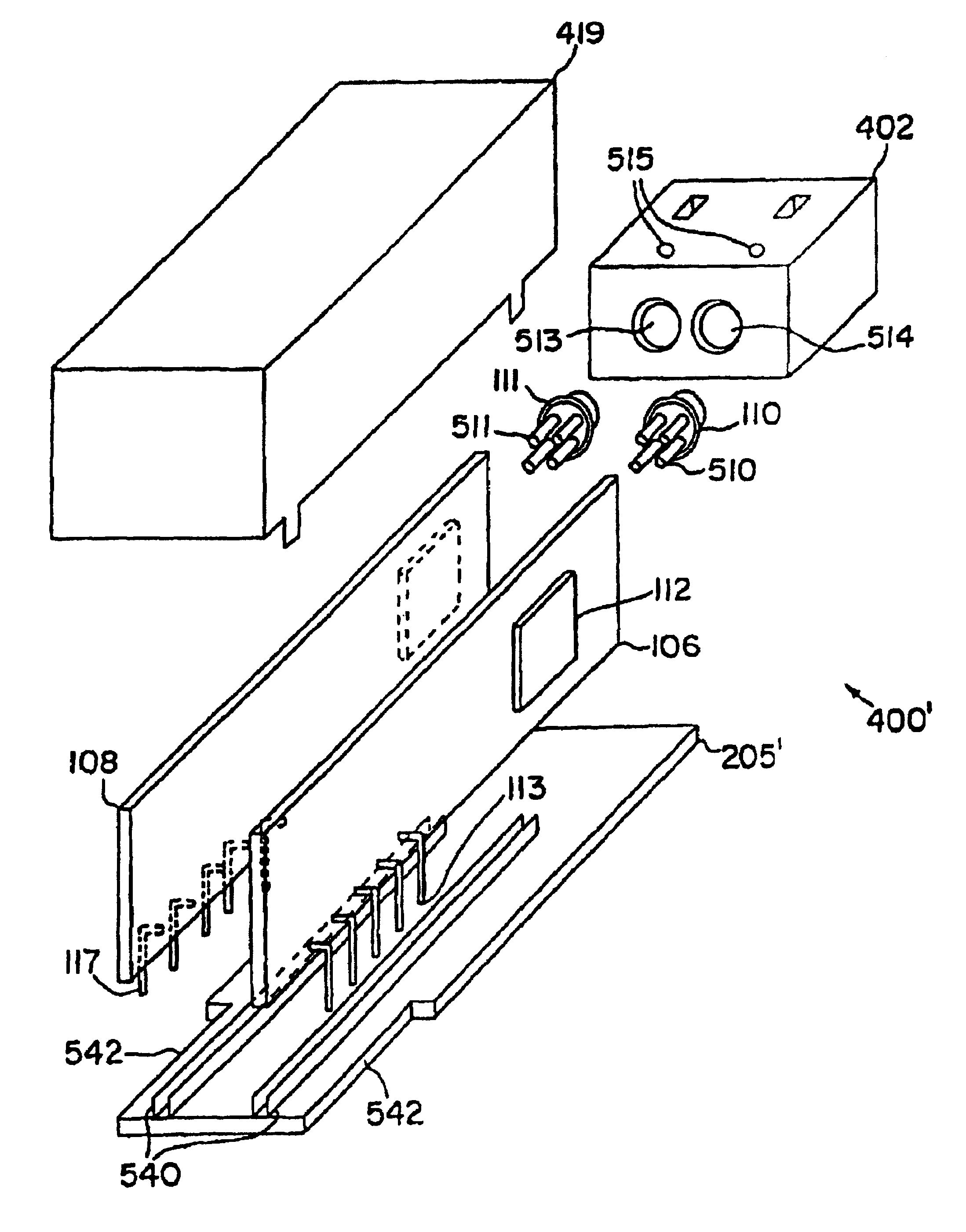
[0065]The embodiments of the invention include a method, apparatus and system for vertical board construction of fiber optic transmitters, receivers and transceivers. Briefly, fiber optic transmitter and receiver electrical elements are implemented on at least two separate printed circuit boards (PCBs) in a fiber optic module. The separate boards are arranged within the fiber optic module to reduce the footprint of the fiber optic module. In one embodiment, bending light or photons through ninety degrees, the light transmitter (a packaged type of emitter) and a light receiver (a packaged type of photodetector) are each mounted substantially perpendicular to the transmit and receive boards respectively such that their active areas are nearly facing each other but offset. A single optical block can be used to implement lenses and reflecting surfaces to minimize manufacturing costs. In one embodiment, the light receiver and light transmitter are mounted offset from each other in the op...

first embodiment

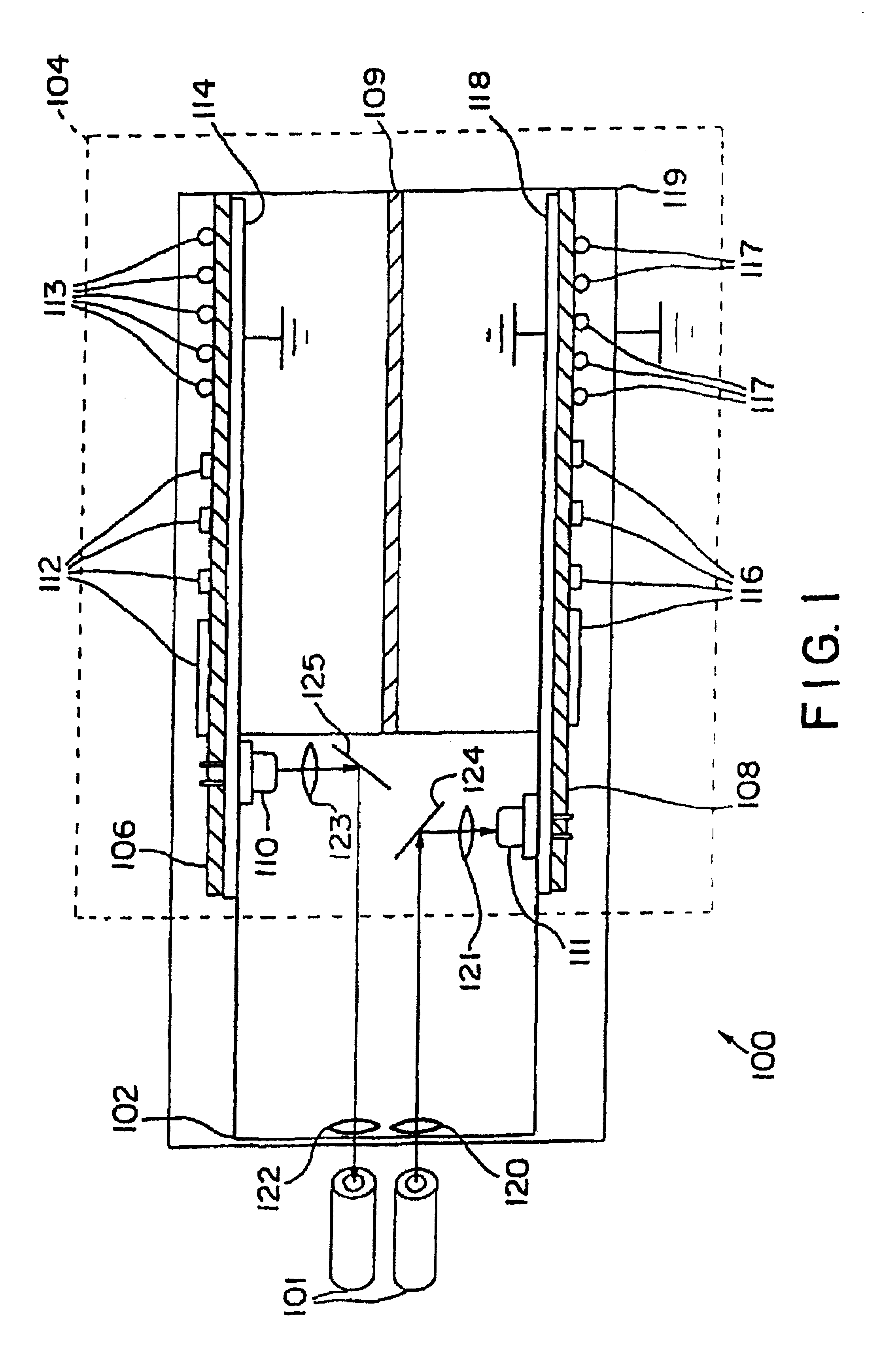
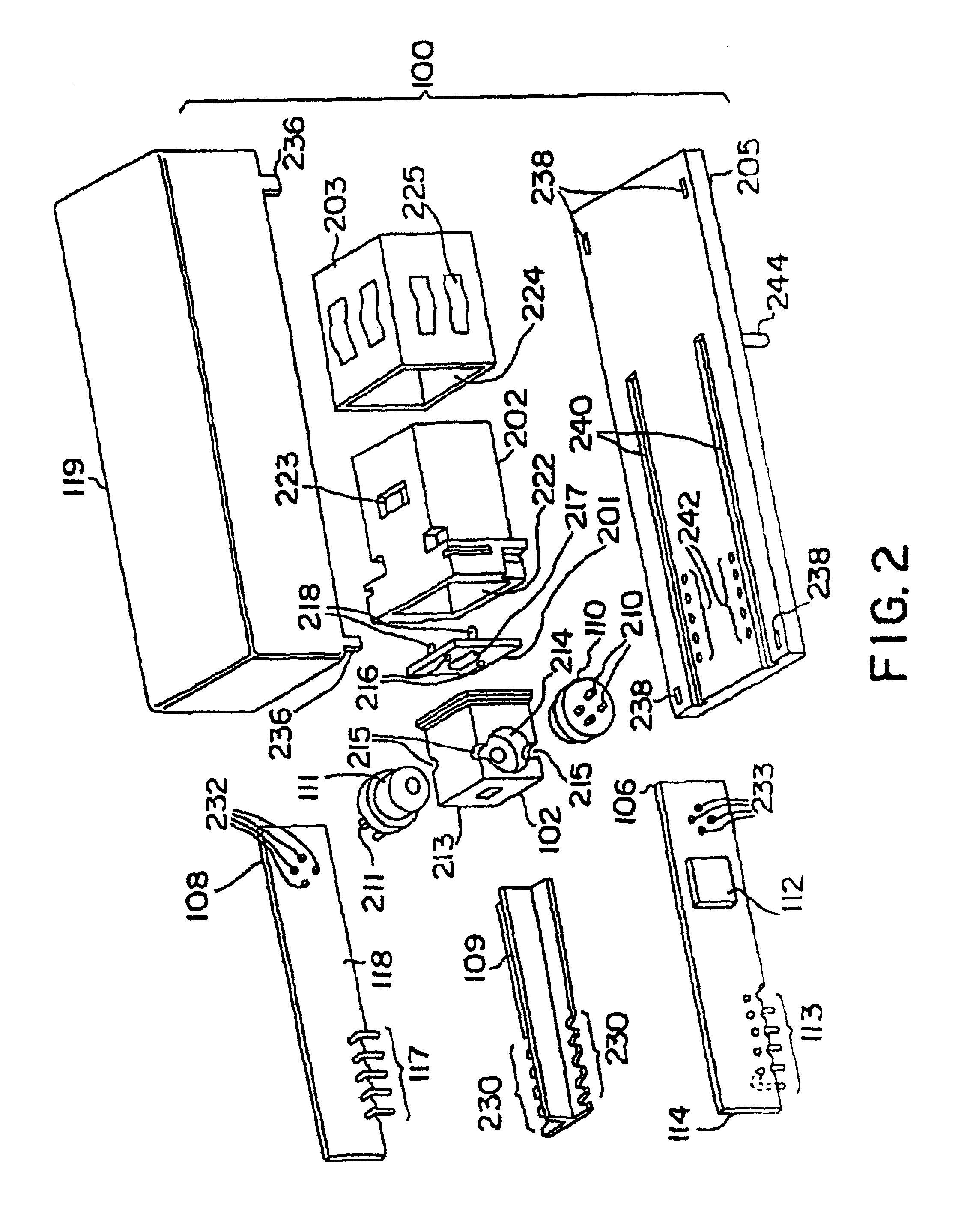
[0066]Referring now to FIG. 1, a simplified cutaway view of the invention is illustrated. FIG. 1 illustrates a fiber optic module 100 coupling to a pair of fiber optic cables 101. Fiber optic module 100 includes an optical block 102 and an electrical element 104. The optical block 102 may also be referred to as a nose, an optical port, an alignment block, an optical connector, an optical receptacle or receptacle. The optical block 102 can interface to an optical connector such as an LC, MT-RJ or VF-45 optical connector. The electrical element 104 includes a transmit printed circuit board (PCB) 106, a receive PCB 108, an optional internal shield 109, a light transmitter 110, a light receiver 111, and a shielded housing or cover 119. The light transmitter 110 and light receiver 111 are optoelectronic devices for communicating with optical fibers using light of various wavelengths or photons. An optoelectronic device is a device which can convert or transduce light or photons into an e...


PUM


Abstract

Pluggable fiber optic modules having a receive printed circuit board and a transmit printed circuit board perpendicular with an interface printed circuit board with an edge connection. The edge connection of the interface printed circuit board to plug into and out from an edge connector of a host printed circuit board. A transmitter optoelectronic device is coupled to the transmit printed circuit board. A receiver optoelectronic device is coupled to the receive printed circuit board. The pluggable fiber optic modules may further include a support base, a nose receptacle, and an alignment plate.

Description

CROSS REFERENCE TO RELATED APPLICATIONS[0001]This U.S. Non-Provisional Patent Application claims the benefit of U.S. Provisional Patent Application No. 60 / 283,046 entitled “METHOD AND APPARATUS FOR PLUGGABLE FIBER OPTIC MODULES”, filed Apr. 10, 2001 by Ron Cheng Pang et al.[0002]This U.S. Non-Provisional Patent Application also claims the benefit of and is a continuation-in-part application of U.S. application Ser. No. 09 / 321,308, entitled “METHOD AND APPARATUS FOR VERTICAL PCB FIBER OPTIC MODULES”, filed May 27, 1999 by inventors Wenbin Jiang et al, and claims the benefit of and is a continuation-in-part application of U.S. application Ser. No. 09 / 656,779, entitled “HOT PLUGGABLE OPTICAL TRANSCEIVER IN A SMALL FORM PLUGGABLE PACKAGE”, filed Sep. 7, 2000 now U.S. Pat. No. 6,873,800, by inventors Wei et al, which is incorporated herein by reference, all of which are to be assigned to E2O Communications, Inc.FIELD OF THE INVENTION[0003]This invention relates to fiber optic modules.BAC...

Claims


Application Information

Patent Timeline
Patent Type & Authority Patents(United States)
IPC IPC(8): H04B10/00G02B6/42
CPCG02B6/4201G02B6/4214G02B6/4246G02B6/4292G02B6/428G02B6/4253G02B6/424G02B6/4257G02B6/4261G02B6/4263G02B6/4277G02B6/4284
Inventor PANG, RON CHENG CHUANSIM, YONG PENGDAIR, EDWINJIANG, WENBINWEI, CHENG PINGTAN, RONSON K.TAN, KEE SIN
Owner LUMENTUM OPERATIONS LLC
Why Eureka
Try Eureka