Current pulse falling edge linear adjustable control method and device having rising edge lifting capacity

A current pulse and linear technology, which is applied in the field of control and device with linearly adjustable falling edge of current pulse with rising edge lifting capability, can solve the problem of affecting the frequency of current pulse, affecting the shape of current pulse, and increasing the time for the current to reach a steady state. And other issues

Active Publication Date: 2007-09-12
CHONGQING CUILU DETECTION TECH CO LTD
View PDF2 Cites 0 Cited by
  • Summary
  • Abstract
  • Description
  • Claims
  • Application Information

AI Technical Summary

Problems solved by technology

[0004] In many cases, the load of the current pulse device is an inductive load, especially when the load is a large inductance load such as a coil, which seriously affects the shape of the current pulse. The current pulse is not an ideal pulse waveform. There is a certain delay time, and the linearity of the current falling edge is poor
The current pulse device is used as a signal source. It is a difficult point in power electronics technology to simultaneously solve the problems of adjustable falling delay time of the current pulse, linearity of the falling edge, and steepness of the rising edge. The delay of the rising edge and the falling edge makes the current reach The time of steady state becomes longer, which affects the increase of current pulse frequency

Method used


Image

  • Current pulse falling edge linear adjustable control method and device having rising edge lifting capacity
  • Current pulse falling edge linear adjustable control method and device having rising edge lifting capacity
  • Current pulse falling edge linear adjustable control method and device having rising edge lifting capacity

Examples


Embodiment Construction

[0081] Concrete control method of the present invention is:

[0082] 1. Close the switch K and adjust the frequency of the "bipolar current pulse control circuit" to 12.5Hz

[0083] 2. Adjust the voltage V of the DC power supply 1 = 38V, the output current pulse amplitude is 57A, and the maximum current through the selected full-control electronic switch is 100A;

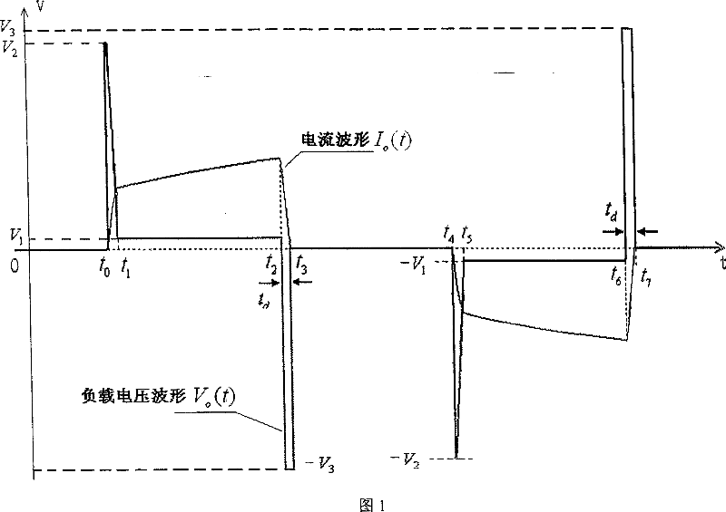
[0084] 3. Output periodic load voltage waveform V o (t) is:

[0085] t 0 :V o =V 2 , V 1 2 3 , the figure is V o =550V;

[0086] t 1 :V o =38V;

[0087] t 2 :V o Reduced from 38V to -600V;

[0088] t 3 :V o Rising from -600V to 0V;

[0089] t 4 :V o From 0V to -550V;

[0090] t 5 :V o = -38V;

[0091] t 6 :V o From -38V to 600V;

[0092] t 7 :V o From 600V to 0V;

[0093] Control voltage and current pulse during rising and falling of positive current pulse:

[0094] at t 0 ~t 1 During, the voltage supplied to the load V o (t) initial value V o (t 0 ) = V 2 =550V, the current pulse...


PUM


Abstract

The present invention is current pulse controlling method and device with rise edge raising capacity and fall edge linearity regulating capacity and current pulse generating method and device, and is especially suitable for the condition with great inductance load in geophysical exploration, engineering geological exploration and other fields. The method of the present invention includes: regulating frequency, regulating the voltage of DC power supply and clamping voltage source to generate voltage waveform with the same shape and amplitude, calculating the fall slope of the positive and negative current pulses and the fall delay time of the output current pulse. The device of the present invention includes DC power source, power switch, bipolar current pulse generator and its control circuit, inductive load, rise edge raising circuit, clamping circuit and clamping voltage source.

Description

Technical field: [0001] The invention relates to a method and a device for generating a current pulse, and is particularly suitable for the method and device for generating a current pulse when a load has a large inductance, and is suitable for the fields of geophysical exploration, engineering geological exploration and the like. Background technique: [0002] In some research and industrial applications, it is necessary to use positive-going current pulses, negative-going current pulses, or bipolar current pulses. The standard waveform of a bipolar current pulse is characterized by a constant amplitude during the output current period, zero current during the no output period, and periodic changes in the current waveform. [0003] The device for generating current pulses can generate positive, negative or bipolar current pulses with adjustable pulse period and amplitude. The circuit for generating bipolar current pulses is realized by a full-bridge circuit, and the switch...

Claims


Application Information

Patent Timeline
Patent Type & Authority Patents(China)
IPC IPC(8): H03K3/01H03K3/012H03K3/017G01V3/00
Inventor 周雒维付志红苏向丰罗强
Owner CHONGQING CUILU DETECTION TECH CO LTD
Why Eureka
Try Eureka