
Lens barrels

A lens barrel and lens technology, applied in installation, shutter, optics, etc., can solve the problems that hinder the thinning and miniaturization of the lens barrel, and achieve the effect of preventing interference

Inactive Publication Date: 2007-09-19
ASIA OPTICAL CO INC
View PDF2 Cites 0 Cited by
  • Summary
  • Abstract
  • Description
  • Claims
  • Application Information

AI Technical Summary

Problems solved by technology

In other words, there is a problem of hindering the thinning and miniaturization of the lens barrel by restricting the straight-forward guidance of the shutter unit inside the lens barrel

Method used


Image

  • Lens barrels
  • Lens barrels
  • Lens barrels

Examples


Embodiment Construction

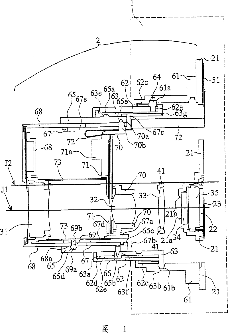
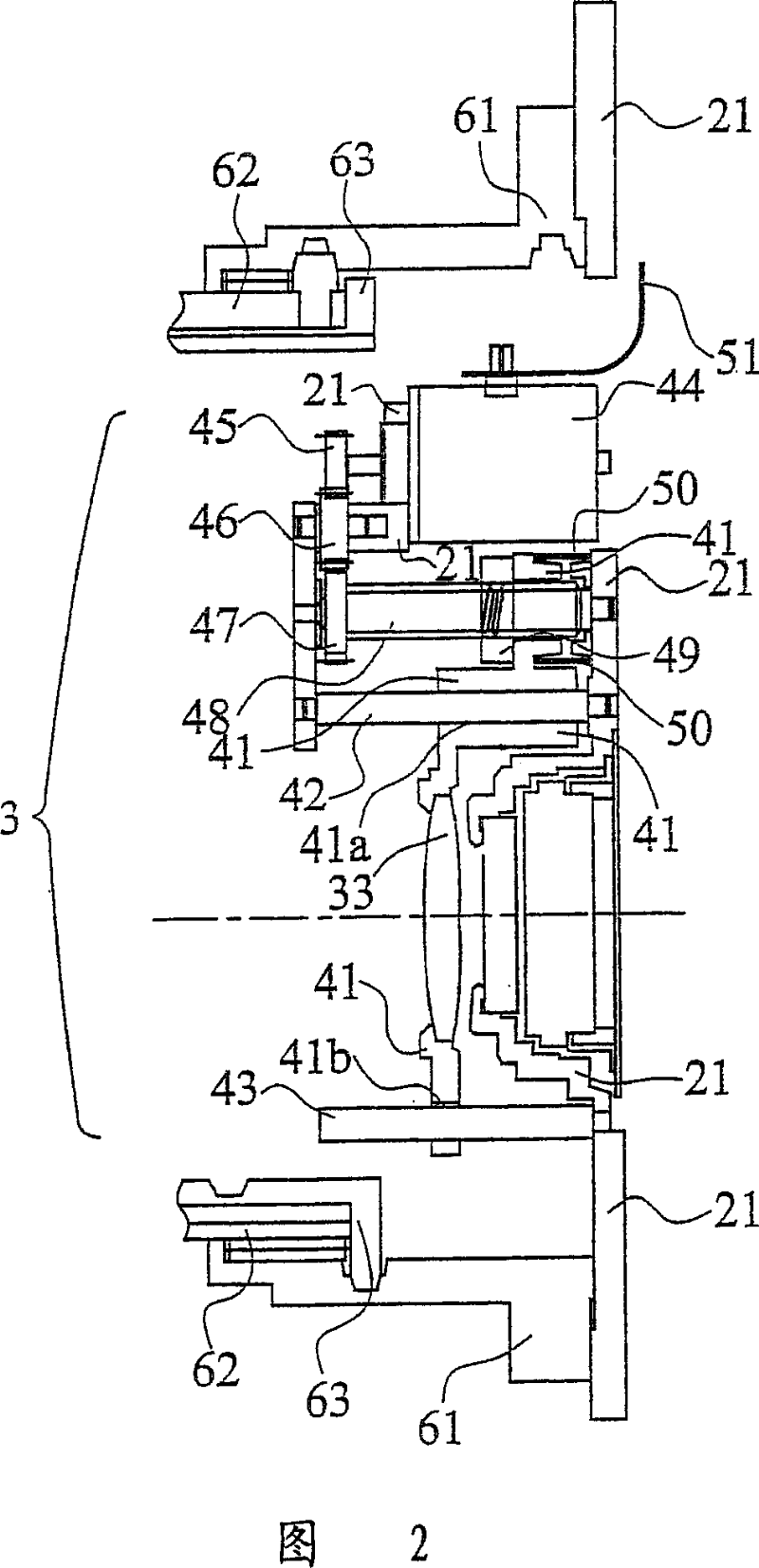
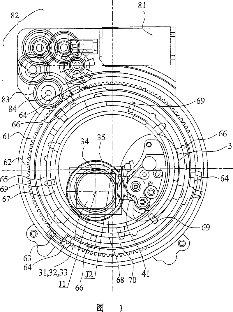
[0042] 1 to 29 illustrate the overall configuration of the lens barrel of this embodiment. In this embodiment, the present invention is applied to a zoom lens barrel for a digital camera.

[0043] FIG. 1 is a cross-sectional view showing the lens barrel 2 in a shooting position on the wide-angle side. The photographing optical system is composed of a first lens group 31, a second lens group 32, a third lens group 33, a low pass filter (low pass filter) 34, and a CCD (photographic device) 35 in order from the subject side. . The optical axis of the photographic optical system is J1. The photographic optical axis J1 is parallel to the central axis J2 of the lens barrel, and is eccentric to the central axis J2. Zooming is performed by moving the first lens group 31 and the second lens group 32 in the direction of the imaging optical axis J1, and focusing is performed by moving the third lens group 33 in the direction of the imaging optical axis J1. Light beams passing through...


PUM


Abstract

PROBLEM TO BE SOLVED: To provide a lens barrel free from the restriction of the movement of a shutter unit.

Description

technical field [0001] The present invention relates to a lens barrel that movably holds a shutter unit. Background technique [0002] The shutter unit with the shutter blades arranged in the lens barrel and the shutter blade drive control circuit arranged in the main body are connected through a flexible printed substrate for signal transmission. When the shutter unit moves in the direction of the imaging optical axis, the flexible printed board for the shutter has a length corresponding to the movement in the direction of the optical axis, and is provided so that no slack occurs. [0003] In addition, when the flexible printed substrate for the shutter moves along the peripheral direction around the central axis of the lens barrel, there are problems such as disconnection and interference with other lens barrel constituent members. 2003-140022 A) is supported by a member that does not rotate, for example, it is supported by a member that moves straight along the direction...

Claims


Application Information

Patent Timeline
Patent Type & Authority Patents(China)
IPC IPC(8): G02B7/04G02B7/10G03B9/08G03B9/10G03B17/04
CPCG03B17/04G03B9/10
Inventor 阪本宇正
Owner ASIA OPTICAL CO INC
Learn More