Optical disk replaying machine and method
A technology of a player, an optical disc, applied in the direction of recording/reproducing by optical methods, recording of information on a magnetic disc, digital recording/reproducing, etc., can solve the problems of influence, large amount of power, harmful sound quality, etc.
Inactive Publication Date: 2007-11-07
SONY CORP
3 Cites 0 Cited by
AI-Extracted Technical Summary
Problems solved by technology
Disc players consume a relatively large amount of power as a whole, and the operation of circuits dedicated to another type of disc can cause the disc player to malfunction and adversely affect any content being played in the disc player. The noise of the circuit in the...
Method used
[0060] In particular, the system controller 11 controls when one of the HD and CD signal processing systems is operated while the other signal control system is in a power saving mode.
[0066] At this time, the system controller 11 controls the CD optical sensor 3B, the CD RF amplifier 4B and the CD signal processor/DAC 7B via the CD control line 14B so that they are respectively in the power saving mode.
[0074] At this point, the system controller 11 will control the HD optical sensor 3A, HD RF amplifier 4A and HD signal processor/DAC 7A via the HD control line 14A to put them in a power saving mode.
[0076] At this time, the system controller 11 will control the CD optical sensor 3B, CD RF amplifier 4B and CD signal processor/DAC 7B via the CD control line 14B to put them in a power saving mode.
[0079] At this point, the system controller 11 will control the HD optical sensor 3A, HD RF amplifier 4A and HD signal processor/DAC 7A via the HD control line 14A to put them in a power saving mode.
[0081] At this time, the system controller 11 will control the CD optical sensor 3B, the CD RF amplifier 4B and the CD signal processor/DAC 7B via the CD control line 14B so that they are in a power saving mode.
[0085] FIG. 5 shows a third method of controlling the dedicated circuit 20 to be in a power saving mode. For this method, a switch 41, a power supply line 42, an oscillator 43 which always generates a clock signal, a low-frequency oscillator 44 which generates a clock signal whose frequency is lower than that generated by the oscillator 43, and a control line 45 (HD or CD control line 14A or 14B). With this method of setting the power saving mode, the switch 41 is wired between the dedicated circuit 20 and the low frequency oscillator 43 and is controlled by the control line 45 to switch from the oscillat...
Abstract
A disc player for selectively reading multi-bit digital signal obtained by sampling with a sampling signal Fs and one-bit digital signal obtained by sampling with a sampling signal nxFs (n is an integer larger than 2), is adapted to control, when one of the digital signals is selected for reading, a signal processing circuit for the other digital signal to stand in a power saving mode, thereby permitting a long time of playing.
Application Domain
Record information storageDigital recording/reproducing +2
Technology Topic
Power savingSignal processing circuits +3
Image
Examples
- Experimental program(1)
Example Embodiment
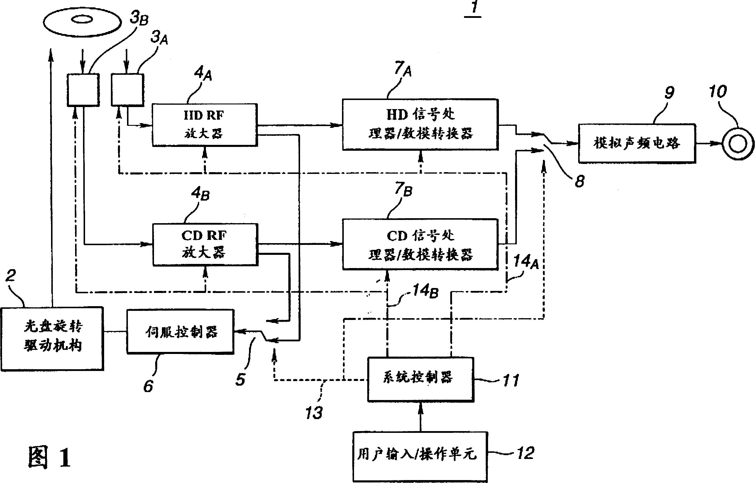
[0045] The invention is further described below in terms of disc players suitable for both types of discs. The compact disc player is adapted to selectively read compact discs (CDs; hereinafter referred to as "CD discs" for ease of illustration and explanation) and high density recording discs and/or have CDs recorded on their first layer. signal, and an HD signal is recorded on its second layer.
[0046] Here, the CD refers to an optical disc having a first audio signal of 16 quantization bits sampled at a sampling frequency of 44.1 KHz recorded therein.
[0047] On the other hand, here, a high density (HD) recording optical disc refers to an optical disc having a second digital audio signal of 1 quantization bit (hereinafter referred to as "HD signal") sampled at a sampling frequency of 64*44.1 KHz.
[0048] Referring now to FIG. 1, there is schematically illustrated in block diagram form an embodiment of an optical disc player according to the present invention suitable for the above-mentioned three types of optical discs. The disc player is indicated generally by reference numeral 1 .
[0049] The disc player 1 includes a disc rotary drive mechanism 2 comprising a motor provided with a turntable adapted to receive each of the three types of discs for driving such a disc mounted thereon. any disc in the .
[0050] The disc player 1 also includes an optical sensor 3A for HD signals. The HD optical sensor 3A emits laser light of 650 nm at the standard readout wavelength shown in Table 1 to the HD signal recording area on the HD disc, and receives an RF signal from light returned from the HD disc. The optical disc player 1 also includes an optical sensor 3B for CD signals. The CD optical sensor 3B emits laser light of 780 nm at the readout wavelength also shown in Table 1 to the CD signal recording area on the CD, and detects an RF signal from light returned from the surface of the CD.
[0051] The HD optical sensor 3A and the CD optical sensor 3B are connected to an RF amplifier 4A for HD signals and an RF amplifier 4B for CD signals, respectively.
[0052] HD and CD RF amplifiers 4A and 4B are dedicated to HD and CD discs, respectively, to provide master content signals and servo signals.
[0053] Servo signals from each of the HD and CD RF amplifiers 4A and 4B are connected to a servo signal selection switch 5 . The servo signal selected by the servo signal selection switch 5 is sent to the servo controller 6 .
[0054] The servo controller 6 controls and drives the disc rotation driving mechanism 2 according to the servo signal selected by the servo signal selection switch 5 and supplied thereto.
[0055] The main signals from the HD and CD RF amplifiers 4A and 4B are also fed to a signal processor/digital-to-analog converter 7A for HD signals and a signal processor/digital-to-analog converter 7B for CD signals, respectively. HD signal processor/DAC 7A and CD signal processor/DAC 7B process the main signals from HD and CD RF amplifiers 4A and 4B respectively according to the corresponding specific signal processing methods shown in Table 1, In order to generate audio signals to be supplied to the output selection switches 8 respectively.
[0056] An output selection switch 8 selects any one of said delivered audio signals for transmission to an analog audio circuit 9 .
[0057] The optical disk player 1 has an output terminal 10 for transmitting audio signals, CD or HD signals.
[0058] The disc player 1 also includes a system controller 11 which supplies various control signals to the CD optical sensor 3B, CD RF amplifier 4B, and CD signal processor/digital-to-analog converter 7B, and to the HD optical sensor 3A, HD RF Amplifier 4A and HD Signal Processor/Digital-to-Analog Converter 7A to control the operation and power mode of these components. The system controller 11 also controls the operation of the servo and output signal selection switches 5 and 8 .
[0059] The disc player 1 also has a user input/operation unit 12 for the user to select which type of disc he or she wishes to play and to start/stop disc playback in the disc player 1 .
[0060] In particular, the system controller 11 controls when one of the HD and CD signal processing systems is operated while the other signal control system is in a power saving mode.
[0061] In the disc player 1, the optical sensor 3A, the RF amplifier 4A, and the signal processor/digital-to-analog converter 7A together constitute a dedicated circuit for HD discs, while the optical sensor 3B, the RF amplifier 4B, and the signal processor/digital-to-analog converter The circuit breaker 7B together constitutes a dedicated circuit for CD discs, and other sub-circuits are commonly used for both HD discs and CD discs.
[0062] Next, the optical disk player 1 constructed as described above will be described.
[0063] When the user wants to play an HD disc using the disc player 1, he issues an HD selection/start command to the disc player 1 using the input/operation unit 12.
[0064] Then, the system controller 11 will set the servo and output signal selection switches 5 and 8 via the HD/CD selection line 13 to appropriate positions with respect to the HD line, respectively. Thus, servo signals are sent from the HD disc provided in the disc rotary drive mechanism 2 to the servo controller 6, while the master disc content is sent to the HD signal processor/DAC 7A via the HD optical sensor 3A and HD RF amplifier 4A.
[0065] The HD signal processor/digital-to-analog converter 7A, which has received the contents of the master disc, provides an analog audio signal which is output at an output terminal 10 via an analog audio circuit 9 .
[0066] At this time, the system controller 11 controls the CD optical sensor 3B, the CD RF amplifier 4B and the CD signal processor/D/A converter 7B via the CD control line 14B so that they are respectively in the power saving mode.
[0067] On the other hand, when the user wants to play a CD using the CD player 1, he issues a CD selection/start command to the CD player 1 using the input/operation unit 12. As mentioned above, the system controller 11 will set the servo and output signal selection switches 5 and 8, respectively, at the appropriate positions with respect to CD routing. Thus, the signal from the CD passes through the CD optical sensor 3B, the CDRF amplifier 4B, the CD signal processor/digital-to-analog converter 7B, and then through the analog audio circuit 9, and is then output at the output terminal 10 in the form of an audio signal. At this time, the system controller 11 controls the HD optical sensor 3A, the HD RF amplifier 4A and the HD signal processor/DAC 7A via the HD control line 14A so that they are respectively in the power saving mode.
[0068] Furthermore, according to the present invention, the disc player 1 can be adapted to automatically distinguish between HD and CD type discs provided in the disc rotation drive mechanism 2 without requiring the user to select the disc type using the input/operation unit 12, and to control the optical sensor , RF amplifiers, and signal processors/digital-to-analog converters, putting them in a power-saving mode. It should be noted that it is also possible to modify the disc player so that, in addition to HD and CD discs, it is also possible to distinguish between hybrid discs having CD and HD signals recorded thereon (hereinafter referred to as "CD/HD multi-layer or hybrid discs"). CD"). In this case, the CD disc and the HD disc are referred to as a CD single-layer disc and an HD single-layer disc, respectively.
[0069] A hybrid optical disc, ie, a CD/HD multi-layer optical disc, includes an HD signal layer and a CD signal layer formed one on top of the other. The signal recorded on the CD signal layer is completely consistent with the compact disc (CD) standard, and thus, can be read out by laser light emitted from the CD optical sensor 4B of the optical disc player 1 .
[0070] On the other hand, the signal on the HD signal layer is read out by laser light emitted from the HD optical sensor 4A of the optical disk player 1 . Generally, a hybrid optical disc has two layers formed one above the other in this order counting from the optical sensor, ie, HD and CD signal layers. The HD signal layer is made of a transparent material through which laser light with a wavelength of 780 nanometers can pass, while laser light with a wavelength of 650 nanometers cannot.
[0071] FIG. 2 is a flow chart of the automatic disc discrimination in the disc player 1 and the power-saving operation of each disc after the discrimination.
[0072] First, in step S1, an optical disc set in the optical disc rotation drive mechanism 2 of the optical disc player 1 is classified into a CD type, an HD type, or a CD/HD type. More specifically, laser light is emitted from each of the HD and CD optical sensors 3A and 3B. If a signal from a returned component of each laser light irradiated to the surface of the disc is detected, it is judged that the disc is a CD/HD hybrid disc. If only a signal is detected from the return component of one of the two lasers irradiated onto the surface of the disc, it is judged that the disc is either a CD type or an HD type single layer disc.
[0073] Now, for example, if it is judged in step S1 that the optical disc set in the optical disc rotation drive mechanism 2 is a CD single-layer disc, the operation procedure goes to step S2, in which two switches 5 and 8 are respectively set at the relevant CD routing Appropriately positioned so that the signal from the CD passes through the CD optical sensor 3B, the CD RF amplifier 4B, the CD signal processor/digital-to-analog converter 7B, then through the analog audio circuit 9, and then at the output terminal 10 in the form of an audio signal output.
[0074] At this time, the system controller 11 will control the HD optical sensor 3A, HD RF amplifier 4A and HD signal processor/DAC 7A via the HD control line 14A to put them in a power saving mode.
[0075] On the contrary, if it is judged in step S1 that the optical disc set in the optical disc rotation drive mechanism 2 is an HD single-layer disc, the operation procedure goes to step S3, wherein the two switches 5 and 8 are respectively set at appropriate positions concerning HD routing. , Like this, the signal from HD disc passes through HD optical sensor 3A, HD RF amplifier 4A, HD signal processor/digital-to-analog converter 7A, then passes through analog audio circuit 9, then outputs at output terminal 10 in the form of audio signal.
[0076] At this time, the system controller 11 will control the CD optical sensor 3B, CD RF amplifier 4B and CD signal processor/DAC 7B via the CD control line 14B to put them in the power saving mode.
[0077] Also, if it is judged in step S1 that the disc set in the disc rotary drive mechanism 2 is a CD/HD hybrid disc, the operation proceeds to step S4 where it is discriminated whether the signal layer selected by the user is a CD layer or an HD layer.
[0078] For example, if it is judged in step S4 that the signal layer selected by the user is a CD signal layer, then the operating procedure goes to step S5, wherein two switches 5 and 8 are respectively set at appropriate positions concerning CD routing, so that The disc signal passes through a CD optical sensor 3B, a CD RF amplifier 4B, a CD signal processor/digital-to-analog converter 7B, and then through an analog audio circuit 9, and is output at an output terminal 10 in the form of an audio signal.
[0079]At this time, the system controller 11 will control the HD optical sensor 3A, HD RF amplifier 4A and HD signal processor/DAC 7A via the HD control line 14A to put them in a power saving mode.
[0080] On the contrary, if it is judged in step S4 that the signal layer selected by the user is an HD signal layer, then the operating procedure goes to step S6, wherein two switches 5 and 8 are respectively set at appropriate positions concerning HD routing, so that the signal from HD The disc signal passes through HD optical sensor 3A, HD RF amplifier 4A, HD signal processor/digital-to-analog converter 7A, then through analog audio circuit 9, and then output at output terminal 10 as an audio signal.
[0081] At this time, the system controller 11 will control the CD optical sensor 3B, CD RF amplifier 4B and CD signal processor/DAC 7B via the CD control line 14B to put them in the power saving mode.
[0082] Below with reference to Figures 3 to 5, some examples are involved to further illustrate how to control the dedicated circuit 20 for each of the CD and HD discs to be in a power-saving mode:
[0083] Figure 3 shows a first method of controlling the dedicated circuit 20 to be in a power saving mode. For this method, as shown in the figure, a dedicated circuit 20 (CD or HD signal processor) is provided in a power supply line 22 with a switch 21 connected to the dedicated circuit. A control line 23 (HD or CD control line 14A or 14B) and a clock line 24 are provided. In this method, the switch 21 in the power supply line 22 is opened via the control line 14A or 14B to disconnect the power supply itself. The dedicated circuit 20 is only supplied with an operating clock via the clock line 24 , and thus does not supply the dedicated circuit 20 with power. Thus, the dedicated circuitry is essentially disabled and is in a power saving mode.
[0084] FIG. 4 shows a second method of controlling the dedicated circuit 20 to place it in a power saving mode. For this second method, as shown in FIG. 4, the dedicated circuit 20 is provided with a switch 31, a power supply line 32, a clock line 33 and a control line 34 (HD or CD control line 14A or 14B). A switch 31 is connected in a clock line 33 . Control line 34 opens switch 31 to remove power from the operating clock, while power line 32 remains connected to dedicated circuit 20 . Power is provided to the dedicated circuit 20, but no operating clock is provided so that it is essentially inoperative and in a power saving mode.
[0085] Fig. 5 shows a third method of controlling the dedicated circuit 20 to be in a power saving mode. For this method, a switch 41, a power supply line 42, an oscillator 43 which always generates a clock signal, a low-frequency oscillator 44 which generates a clock signal whose frequency is lower than that generated by the oscillator 43, and a control line 45 (HD or CD control line 14A or 14B). With this method of setting the power saving mode, the switch 41 is wired between the dedicated circuit 20 and the low frequency oscillator 43 and is controlled by the control line 45 to switch from the oscillator 43 to the oscillator 44 . That is, the operation of the dedicated circuit 20 is not completely prevented, but the power consumption of the semiconductor circuit is reduced.
[0086] Each of the above methods can achieve the power saving by putting the dedicated circuit 20 which is not the disc or signal layer to be read in an inactive state, while not operating it in the normal mode. It should be noted that this power saving can also be achieved by sampling the transfer of an inactivity command, such as a shutdown command or a sleep command, to the dedicated circuit 20 via the control lines in order to switch the dedicated circuit 20 into a power saving mode.
[0087] In the optical disk player 1 that has been described above, although more than one type of audio optical disk, including CDs having signals recorded thereon according to different optical recording methods, are provided on the same optical disk rotation drive mechanism 2 and a selected one of the HD disc and the hybrid disc is being played back, or, while being read from one of the signal layers of the hybrid disc, information such as The electrical signal detecting means of the optical sensor, the electrical signal amplifying means such as an RF amplifier, and the electrical signal processing means such as a signal processor/digital-to-analog converter are set in a power saving mode, making it possible to reduce the overall Minimize power consumption, avoid dissipating excessive heat, avoid malfunctions caused by energized parts of the disc player circuitry not designated for the disc or signal layer currently being played back or read, and avoid noise entering the disc currently being reproduced or read. The circuit part of the optical disc or signal layer that is played or read.
[0088] In general, with respect to audio disc players, it is generally believed that powering on and activating circuit blocks in the machine that are not required for the disc or signal layer currently being played back or read out will generate excessive heat and cause damage to Noise that has a detrimental effect on the sound quality of the reproduced audio signal. Therefore, the present invention can effectively eliminate this effect in a high-fidelity optical disc player.
[0089] It should be noted that although the optical disc player according to the present invention has been described above with reference to FIG. HD discs are also suitable for CD discs with shorter wavelength lasers.
[0090] Similarly, a 1-bit type DAC would be suitable for both HD and CD discs if used in a signal processor/DAC. Thus, the classification of disc player components into specific blocks and general purpose blocks depends on the actual choice of inheritance of these components. However, dedicated circuitry for HD or CD discs or signal layers that are not being played or read can be set inactive by selecting either of the HD and CD discs. It should also be noted that all or part of the dedicated circuitry may be made inactive for power saving purposes.
[0091] That is, although in the above-described embodiments, when one of the different digital signals is read out, all dedicated circuits for the other digital signal, including optical sensors, RF amplifiers, and signal processors/digital-to-analog converters are However, it is also possible to design the optical disk player according to the present invention so that some parts of the dedicated circuit for another digital signal are controlled to save power.
[0092] Furthermore, the above has been described in relation to optical disc players suitable for HD, CD and hybrid (CD/HD) optical discs. However, similarly, according to the present invention, it is possible to realize an optical disc player suitable for more than 4 kinds of optical discs.
[0093] As described above, the present invention provides an optical disc player modified so that when more than one type of audio optical discs having signals recorded thereon respectively according to different optical recording methods is selected one being read, or, when a selected one of more than one type of audio signal is being read, limiting the power to the signal processing system with respect to the other disc or with respect to the other signal so that the The signal processing system is in a power-saving mode, thereby making it possible to avoid an increase in the overall power consumption of the optical disc player 1 that might otherwise occur, by or read disc or signal but is caused by a part of the disc player circuit that is powered on, and it is possible to avoid the appearance of noise, which may otherwise enter into the disc or signal currently being played or read. The circuit part of the signal.
PUM


Description & Claims & Application Information
We can also present the details of the Description, Claims and Application information to help users get a comprehensive understanding of the technical details of the patent, such as background art, summary of invention, brief description of drawings, description of embodiments, and other original content. On the other hand, users can also determine the specific scope of protection of the technology through the list of claims; as well as understand the changes in the life cycle of the technology with the presentation of the patent timeline. Login to view more.