
Dynamic frame rate adjustment

a dynamic frame rate and adjustment technology, applied in the field of dynamic frame rate adjustment, can solve the problems of display power consumption, display refresh rate changes that cannot be gracefully supported, and display corruption,

Inactive Publication Date: 2008-03-06
ATI TECH INC
View PDF10 Cites 194 Cited by
  • Summary
  • Abstract
  • Description
  • Claims
  • Application Information

AI Technical Summary

Problems solved by technology

Traditionally, displays do not gracefully support changes in the display refresh rate.
During a rate change, they typically go blank and / or display corrupted images.
Further still, displays are known to consume power based, in part, on how frequently they are refreshed; higher refresh rates consume more power, whereas lower rates consume less.
However, each display requires a full resolution frame buffer thereby adding to the cost of the display.
However, these systems do not couple the display rate to the image rate for any other type of content, e.g., video image rate, nor are they configured to provide power savings.
In analog TV, this results in a period of corrupted images while the system adapts to the new frame rate.
However, such systems cover only a fairly narrow range of vertical frequencies (related to the refresh rates) and no display refresh rate adjustment is done for power saving.
Even for digital TV systems that can smoothly adjust the display rate to match the input image rate, it is still expected that these systems (like analog TVs) can only work with a narrow range of vertical rates, and they do not take power savings into account.
However the results are still inferior to systems without these capabilities, and no power savings are taken into account.
However, the frame buffer in the display adds to the cost and power consumption of the display and, given that the display rate is fixed, no power is saved through control of the refresh rate.
However, this idea does not work with content comprising moving images, or at the least, will result in visual artifacts.
Further still, this approach does not help with matching image rates of other content to the display refresh rate (or vice versa).

Method used


Image

  • Dynamic frame rate adjustment
  • Dynamic frame rate adjustment
  • Dynamic frame rate adjustment

Examples


Embodiment Construction

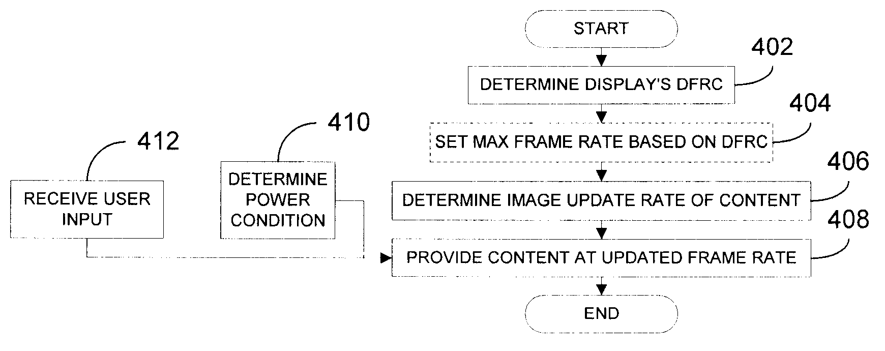
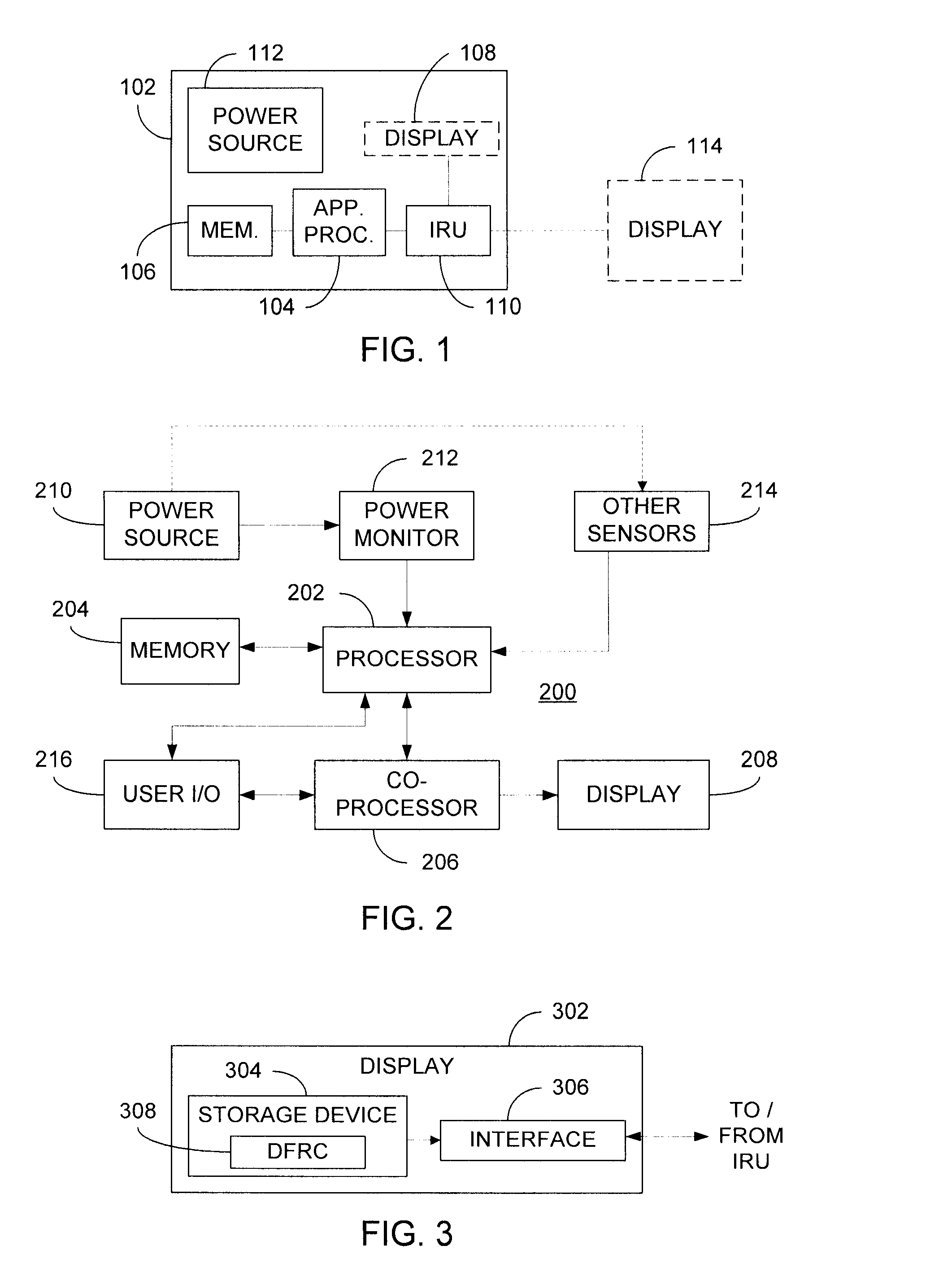
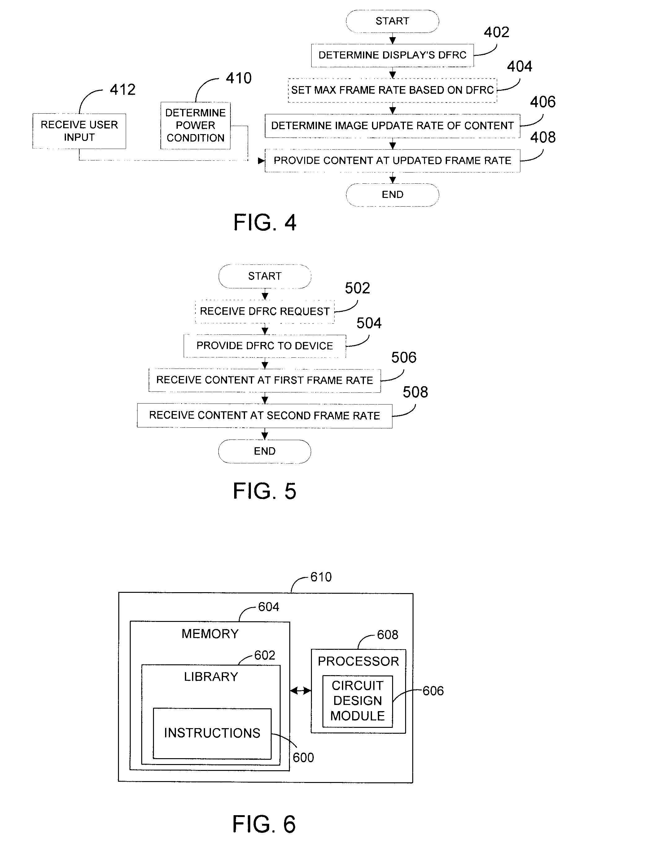
[0017]Briefly, the present invention provides a technique for dynamically adjusting frame rate of a display based at least in part upon the image rate of content to be displayed thereon. Where a given display, which may be integral with or external to a device, possesses dynamic frame rate capabilities, an image rendering unit (IRU) of the device can determine the dynamic frame rate capabilities (DFRCs) of the display and additionally determine an image frame rate of content to be displayed. The DFRCs can be pre-stored in memory associated with or otherwise available to the IRU, including storage devices that may be deployed within the display itself. Based on the DFRCs and the image frame rate for the content, the IRU determines an updated frame rate and thereafter provides the content to the display at the updated frame rate. Where control of power consumption is desired, a maximum frame rate of the display can be set as the initial frame rate although, of course, other frame rate...


PUM


Abstract

An image rendering unit (IRU) of a device determines the dynamic frame rate capabilities (DFRCs) of a display and an image frame rate of content to be displayed. Preferably, the DFRCs are stored in a storage device deployed within the display itself. Based on the DFRCs and the image frame rate for the content, the IRU determines an updated frame rate and thereafter provides the content to the display at the updated frame rate. Where control of power consumption is desired, selection of a reduced frame rate can effect a power savings. In this manner, the present invention provides flexible control over display frame rates and / or power consumption of the device.

Description

FIELD OF THE INVENTION[0001]The present invention relates generally to providing content to displays and, in particular, to techniques for dynamically adjusting frame rates at which content is displayed.BACKGROUND OF THE INVENTION[0002]As known in the art, images are provided to displays, such as computer or television (TV) displays, many times per second, i.e., at the display refresh or frame rate. Traditionally, displays do not gracefully support changes in the display refresh rate. During a rate change, they typically go blank and / or display corrupted images. As a result, such rate changes are performed relatively rarely, e.g., when changing the display mode, starting or stopping a full screen application (such as a video game) or when changing the power source between alternating current (AC) and direct current (DC).[0003]It is also known that moving images appear best to the human eye when the display refresh rate matches the image update or frame rate (i.e., the rate at which ...

Claims


Application Information

Patent Timeline
IPC IPC(8): G06T1/00
CPCG09G3/20G09G2340/0435H04N5/46H04N7/0127H04N21/440281H04N21/4436H04N21/4621H04N21/4122
Inventor GLEN, DAVID I.J.
Owner ATI TECH INC
Learn More