CD recording signal control circuit

A signal control circuit and signal technology, applied in the direction of optical recording system, recording information storage, optical recording/reproduction, etc., can solve the problems of drive signal deformation, data error, etc.

Inactive Publication Date: 2007-11-21
MEDIATEK INC
View PDF6 Cites 0 Cited by
  • Summary
  • Abstract
  • Description
  • Claims
  • Application Information

AI Technical Summary

Problems solved by technology

As shown in Figure 3, since the duty cycle of the three programming signals WS1, WS2, and WS3 is not 50%, the driving signal generated by the LD drive unit has been seriously deformed
If the optical drive drives the laser light source 14 with this distorted driving signal, the burned data may be wrong, which will cause data errors when reading the optical disc later.

Method used


Image

  • CD recording signal control circuit
  • CD recording signal control circuit
  • CD recording signal control circuit

Examples


Embodiment Construction

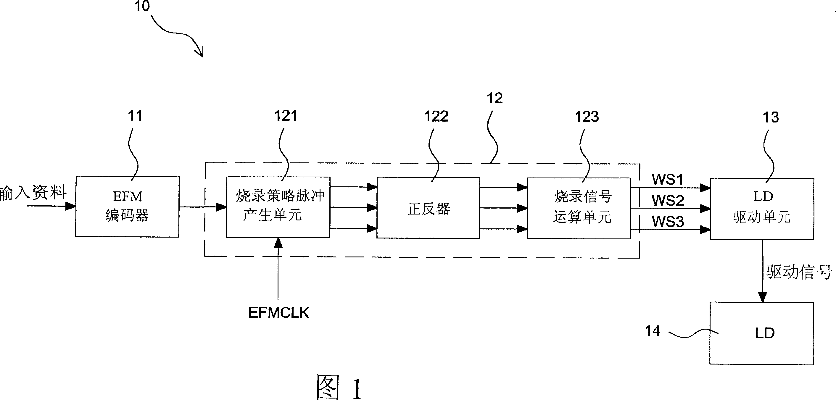
[0045] Since the conventional programming signal control circuit directly outputs the programming signal to the LD drive unit after generating the programming signal, there is no further detection of whether the duty cycle of the programming signal is average. Therefore, the programming signal control circuit may cause distortion of the programming signal or uneven duty cycle due to errors in digital logic gates, buffers, and output drive units. Therefore, in order to solve this problem, the present invention particularly utilizes a duty cycle detection unit to detect the duty cycle of the programming signal, and utilizes the duty cycle adjustment unit to adjust the duty cycle of the programming signal, so that the programming output to the LD drive unit The duty cycle of the signal can be correct.

[0046]FIG. 4 shows a block diagram of the programming signal control circuit of the present invention. The programming signal control circuit 40 includes an EFM encoder 41 , a pr...


PUM


Abstract

It is a kind of CD-recording signal control circuit that adjusts the responsibility cycle of recording signal by one responsibility cycle adjusting unit. This CD-recording signal control circuit comprising: one EFM encoder receive the imported signal and encode it to EFM signal; one recording strategic wave generating unit receive the EFM signal and generate several groups of recording signals according to this EFM signal; one responsibility cycle adjusting unit receive these recording signals and adjust the responsibility cycle of these recording signals and export them as several groups of adjusted recording signals; one responsibility cycle detecting unit receive several groups of adjusted recording signals that exported by the responsibility cycle adjusting unit and detect the responsibility cycle of several groups of adjusted recording signals and export the responsibility cycle adjusted signal. This responsibility cycle adjusting unit also receive responsibility cycle adjusted signal to adjust the responsibility cycle of several groups of recording signals.

Description

technical field [0001] The invention relates to an optical disc burning signal control circuit. Background technique [0002] FIG. 1 shows a block diagram of a recording signal control circuit in a general optical disc recording device. As shown in the figure, the programming signal control circuit 10 includes an EFM encoder (Eight-to-Fourteen Modulation encoder) 11, a programming strategy waveform generator (write strategy waveform generator) 12, an LD driver unit (Laser diode driver) ) 13, and a laser light source (LD) 14. The EFM encoder 11 receives input data to be programmed, and generates an EFM signal according to an EFM encoding rule. The writing strategy waveform generation unit 12 receives the EFM signal, and generates a plurality of writing signals (write signals) according to the EFM signal and the characteristics of the disk to be written, for example, three writing signals as shown in FIG. 1 . The programming strategy waveform generating unit 12 generally in...

Claims


Application Information

Patent Timeline
Patent Type & Authority Patents(China)
IPC IPC(8): G11B7/0045G11B7/00
Inventor 徐哲祥陈志成刘元卿
Owner MEDIATEK INC
Why Eureka
Try Eureka