CD recording/reproducing equipment and method thereof

A technology for recording and reproducing optical discs, which is applied in the directions of recording/reproducing by optical methods, optical recording heads, optical recording carriers, etc., and can solve problems such as difficulty in ensuring assembly accuracy and complex structure.

Inactive Publication Date: 2003-08-20
SONY CORP
View PDF1 Cites 0 Cited by
  • Summary
  • Abstract
  • Description
  • Claims
  • Application Information

AI Technical Summary

Problems solved by technology

If an adjuster is used to adjust the distance between the two lenses of the two-lens unit to adapt to changes in the thickness of the optical disc, a complicated structure is required and it is difficult to ensure the accuracy of the assembly

Method used


Image

  • CD recording/reproducing equipment and method thereof
  • CD recording/reproducing equipment and method thereof
  • CD recording/reproducing equipment and method thereof

Examples


Embodiment Construction

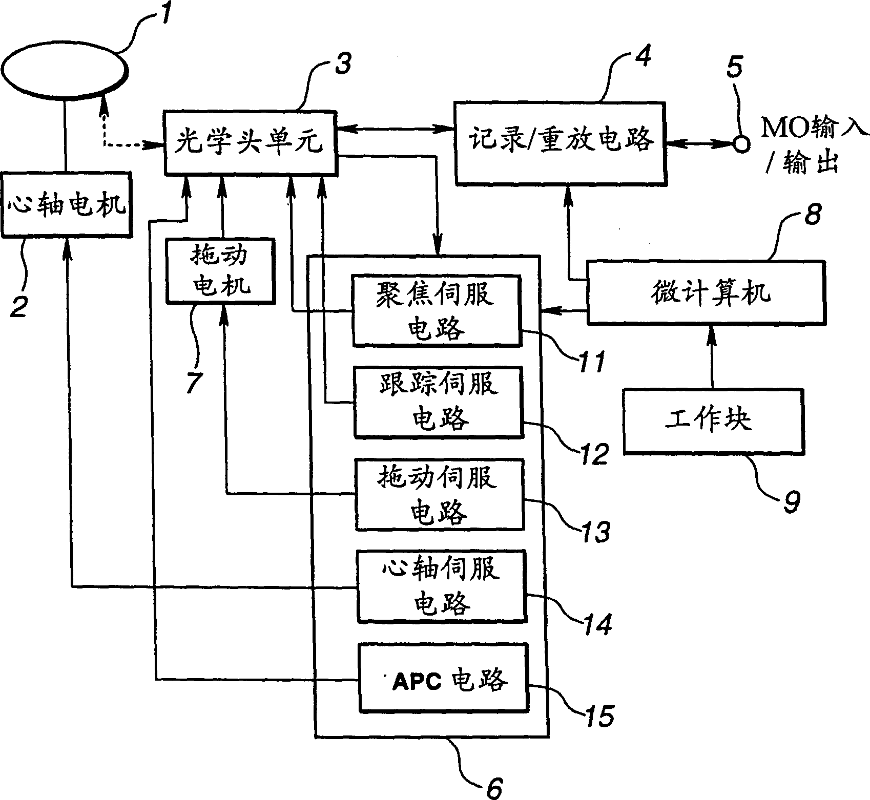
[0031] figure 1 is a block diagram showing the structure of the optical disc recording / reproducing apparatus of the embodiment of the present invention. It should be noted that the following description is made for the case where the magneto-optical disc is used as an optical disc. The magneto-optical disc 1 is rotated by the spindle motor 2 at a predetermined speed. The optical head unit 3 applies a laser beam and a magnetic field to the magneto-optical disc 1 for recording or reproducing data to / from the magneto-optical disc. The recording / reproducing circuit 4 modulates the recording signal applied from the terminal 5 so as to apply the modulated signal to the optical head unit 3; output.

[0032] The servo circuit 6 includes a focus servo circuit 11 , a tracking servo circuit 12 , a drag servo circuit 13 , a spindle servo circuit 14 , and an automatic power control (APC) circuit 15 . The servo circuit 6 reproduces a predetermined error signal from the signal output by ...


PUM

PropertyMeasurementUnit
thicknessaaaaaaaaaa
thicknessaaaaaaaaaa
thicknessaaaaaaaaaa

Abstract

An optical disc recording / reproduction apparatus for recording and / or reproducing a data by applying a beam from an optical head unit through a substrate onto / from a recording layer of the optical disc through, wherein the substrate of the optical disc is 0.3 mm or below; the optical head unit comprises: an objective lens for converging an incident beam and emitting the beam toward the optical disc; a forward lens for converging the beam introduced through the objective lens and applying the beam to the optical disc; a lens holder where the objective lens and the forward lens are fixed; and an actuator for driving the objective lens and the forward lens as a unitary block and controlling at least focusing, the objective lens and the forward lens having a total numerical aperture of 0.8 or above.

Description

technical field [0001] The present invention relates to an optical disc recording / reproducing apparatus and method, in particular to an optical disc recording / reproducing apparatus and method capable of recording or reproducing data to / from a high-density optical disc. Background technique [0002] In order to record or reproduce data to / from a high density optical disc, it is necessary to minimize the size of the light spot applied to the optical disc. It is well known that the size of the light spot is proportional to λ / NA, where λ is the wavelength of the light source and NA is the numerical aperture of the objective lens. Therefore, when the wavelength is constant, an increase in the numerical aperture of the objective lens can increase the recording density. For manufacturing reasons, objectives used as aspheric singlets in currently available optical discs are believed to only have a numerical aperture of at most 0.6. [0003] Furthermore, as the numerical aperture ...

Claims


Application Information

Patent Timeline
Patent Type & Authority Patents(China)
IPC IPC(8): G11B7/135G11B7/09G11B7/125G11B7/1372G11B7/1374G11B7/24G11B11/105
CPCG11B7/1374G11B11/10543G11B7/0935G11B2007/13727G11B7/24G11B11/10576B82Y10/00G11B7/093G11B7/0933G11B7/24047
Inventor 市村功前田史贞山本键二大里洁渡边俊夫铃木彰
Owner SONY CORP
Why Eureka
Try Eureka