Dust collecting unit in suction cleaner

A technology for vacuum cleaners and dust collection chambers, which is applied in the field of vacuum cleaners, can solve the problems of polluted dust collection chambers, doubts about the performance of cyclone-type vacuum cleaners, insufficient cleaning power of the vacuum cleaners, etc., and achieves the effect of increasing the maximum ash storage capacity.

Inactive Publication Date: 2008-01-02
LG ELECTRONICS (TIANJIN) APPLIANCES CO LTD
View PDF3 Cites 0 Cited by
  • Summary
  • Abstract
  • Description
  • Claims
  • Application Information

AI Technical Summary

Problems solved by technology

Therefore can pollute the inwall of dust collecting cavity 13 gradually
In addition, because tiny dust cannot fall and accumulate on the bottom surface of the dust collection chamber 13, users may misunderstand that the cleaning power of the vacuum cleaner is not enough, and thus doubt the performance of the cyclone separator vacuum cleaner.

Method used


Image

  • Dust collecting unit in suction cleaner
  • Dust collecting unit in suction cleaner

Examples


Embodiment Construction

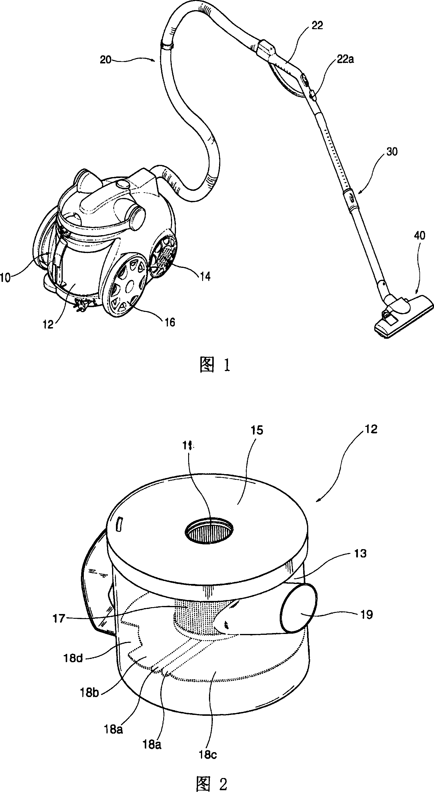
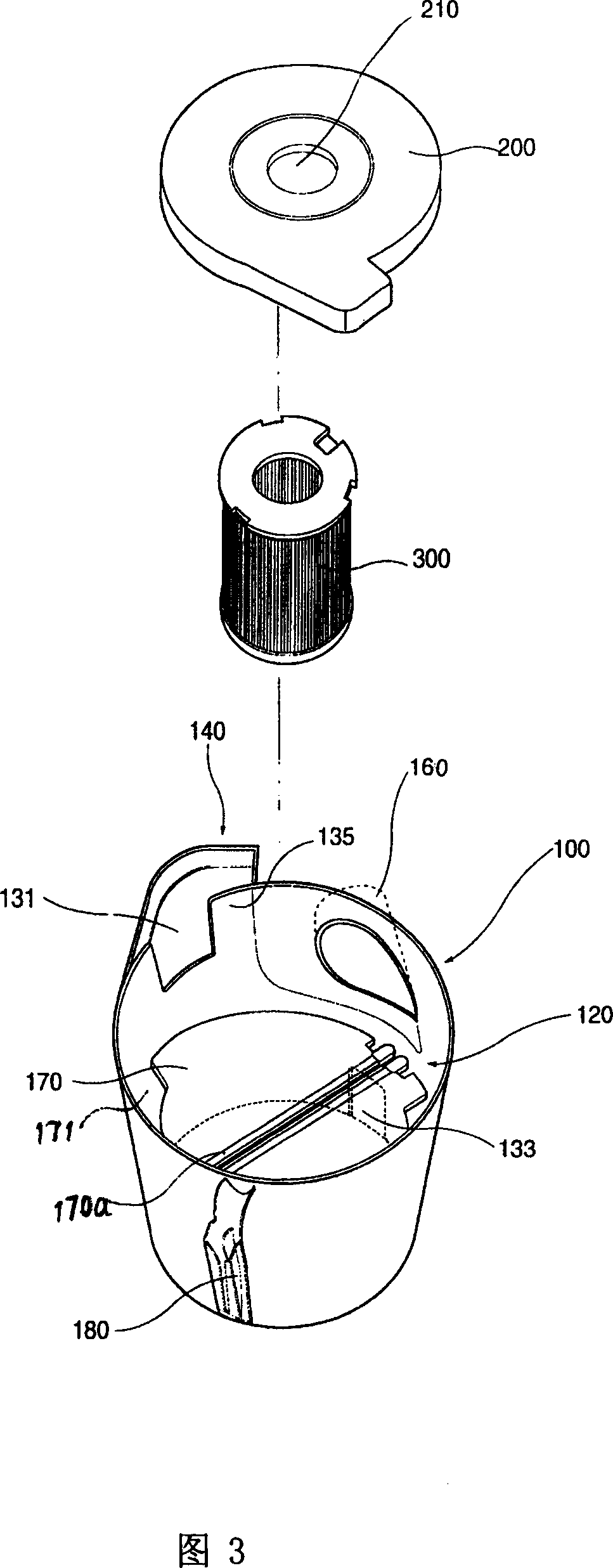
[0033] The present invention will be further described in detail below with reference to the drawings and specific embodiments: Fig. 3 is an exploded schematic diagram of the dust collection unit provided by the present invention. As shown in Fig. 3, the dust collection unit provided by the present invention includes a dust collection chamber 100 with an open upper part, a cover 200, and a filter element 300. The cover 200 is provided on the opening above the dust collection chamber 100 to open and close the dust collection chamber 100. The filter element 300 is arranged on the cover 200 to filter the air to be discharged.

[0034] The dust collection chamber is provided with an inflow port 160 through which foreign matter flows, and a main dust collection chamber 120, a secondary dust collection chamber 140 and other structures for storing foreign matter. In order to allow the air mixed with dust flowing into the dust collection chamber 100 to form a vortex along the inner side w...


PUM


Abstract

A dust collecting unit of cleaner is composed of a dust collecting cavity which consists of inlet, primary and secondary dust-collecting cavities, partition, and upper and lower communicating holes, a cover with central hole, a cylindrical filter core, and a semi-circular separation plate.

Description

Technical field [0001] The invention relates to field vacuum cleaners. Background technique [0002] The vacuum cleaner is a small home appliance that generates negative pressure by a fan motor provided on the main body of the vacuum cleaner, and uses the negative pressure to suck air containing foreign matter, and then filter these foreign matter inside the main body of the vacuum cleaner. Among the recently proposed vacuum cleaners, there is a vacuum cleaner that uses a cyclone to perform filtration. The vacuum cleaner does not use a dust bag. The vacuum cleaner shown in Fig. 1 is a vacuum cleaner using this cyclone filter method. [0003] As shown in the figure, the vacuum cleaner includes a vacuum cleaner main body 10, a connection hose 20, a retractable tube 30, and a dust suction head 40. A fan motor is provided in the main body 10 of the vacuum cleaner to suck indoor air. The connection hose 20 communicates with the inside of the cleaner body 10. The length-adjustable tele...

Claims


Application Information

Patent Timeline
Patent Type & Authority Patents(China)
IPC IPC(8): A47L9/16
Inventor 河建虎
Owner LG ELECTRONICS (TIANJIN) APPLIANCES CO LTD
Why Eureka
Try Eureka