Supercharge Your Innovation With Domain-Expert AI Agents!

Housing for tubine blade and assembling method thereof

A cover and blade technology, applied in the direction of blade support elements, machines/engines, mechanical equipment, etc., can solve problems such as expensive, labor-intensive, etc.

Inactive Publication Date: 2008-01-02
GENERAL ELECTRIC CO
View PDF7 Cites 0 Cited by
  • Summary
  • Abstract
  • Description
  • Claims
  • Application Information

AI Technical Summary

Problems solved by technology

This process is labor intensive and expensive

Method used


Image

  • Housing for tubine blade and assembling method thereof
  • Housing for tubine blade and assembling method thereof
  • Housing for tubine blade and assembling method thereof

Examples


Embodiment Construction

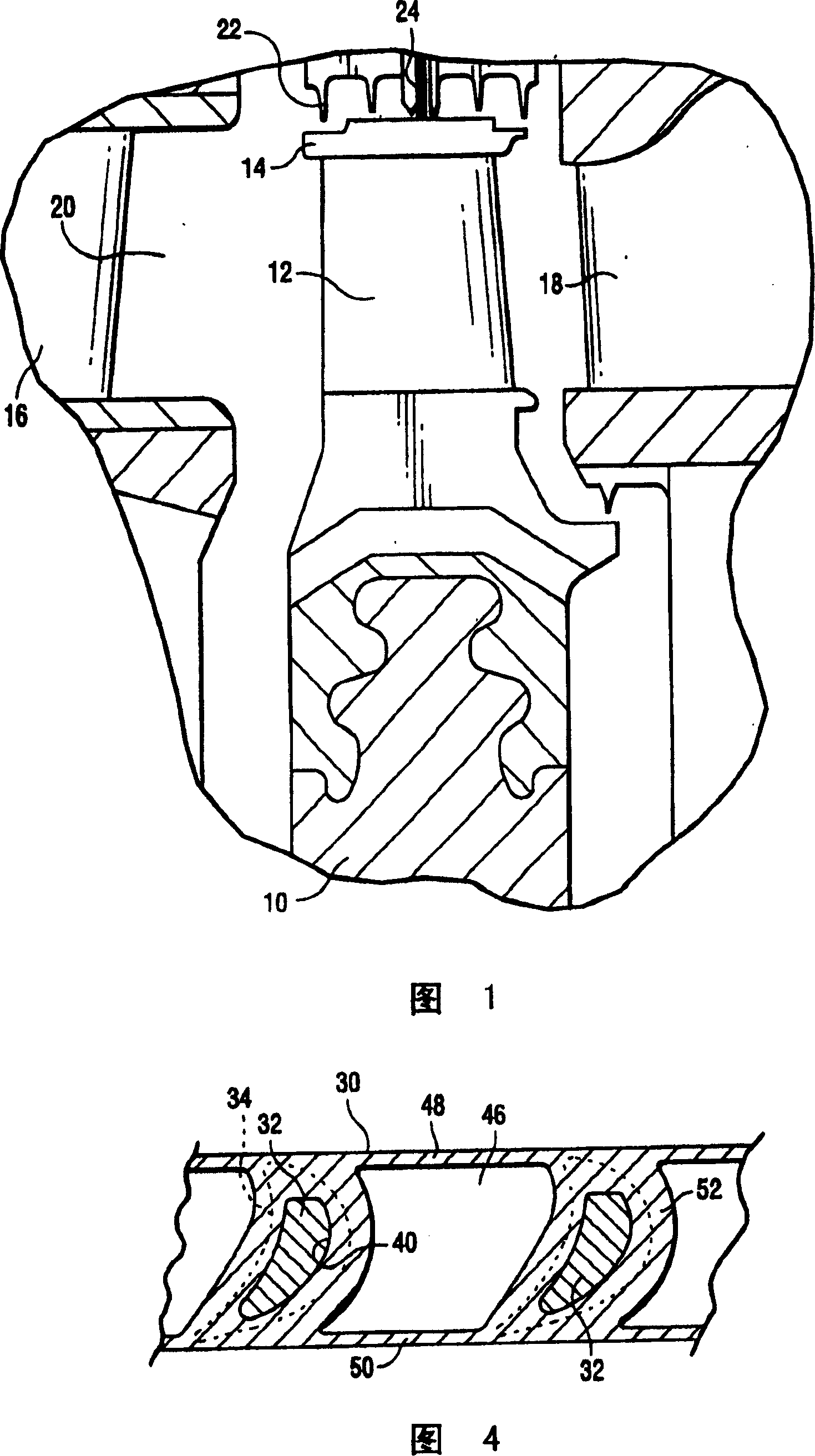
[0015] Referring now to the drawings, and in particular to FIG. 1 , there is shown mounted a plurality of circumferentially spaced blades, one of which is indicated at 12 and has a blade shroud 14 . The axially adjacent stator blades 16 and 18 of the stationary member of the turbine are also revealed in the turbine flow path 20 . A labyrinth seal 22 and a brush seal 24 are shown for sealing around the shroud 14 during operation of the turbine.

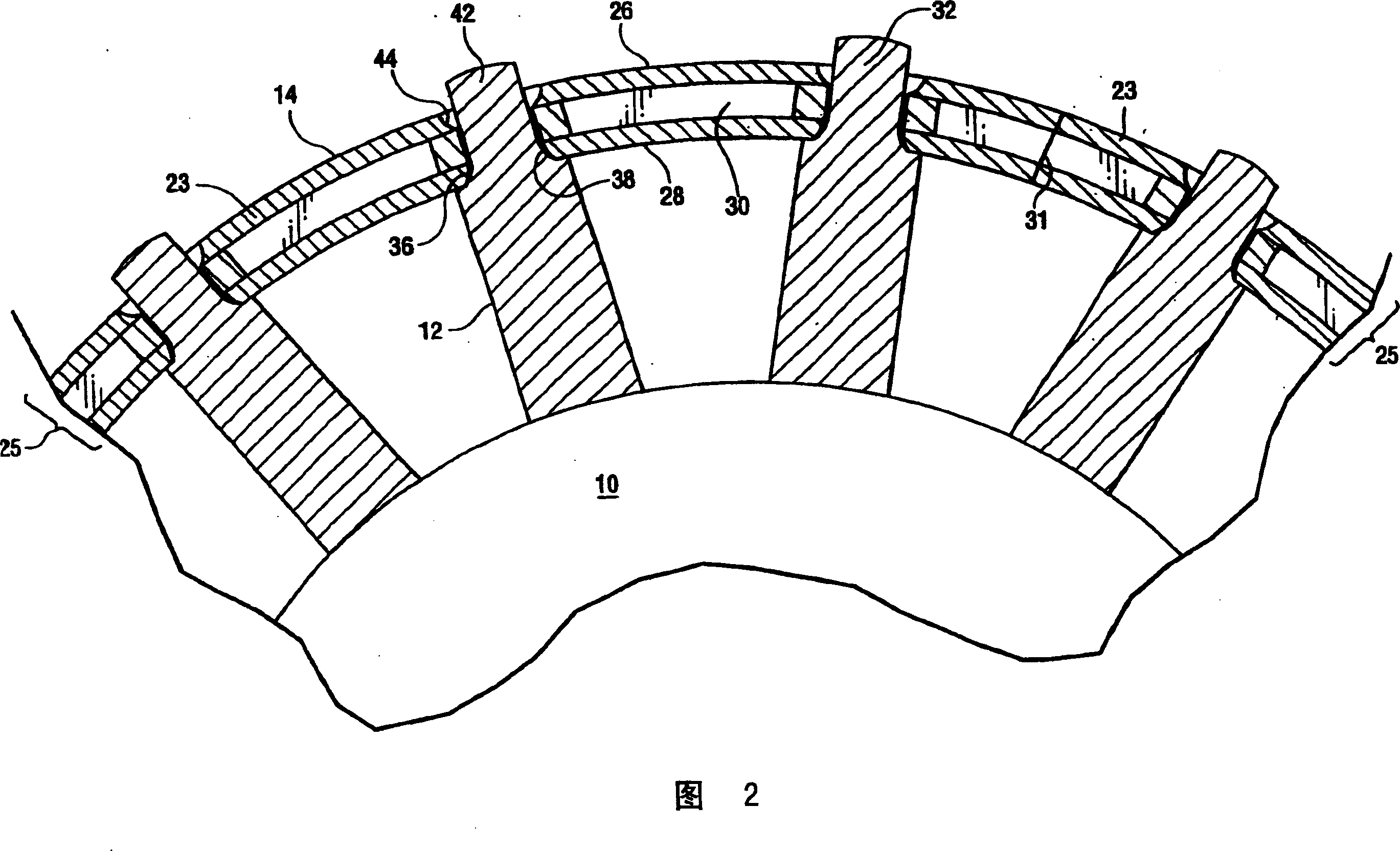
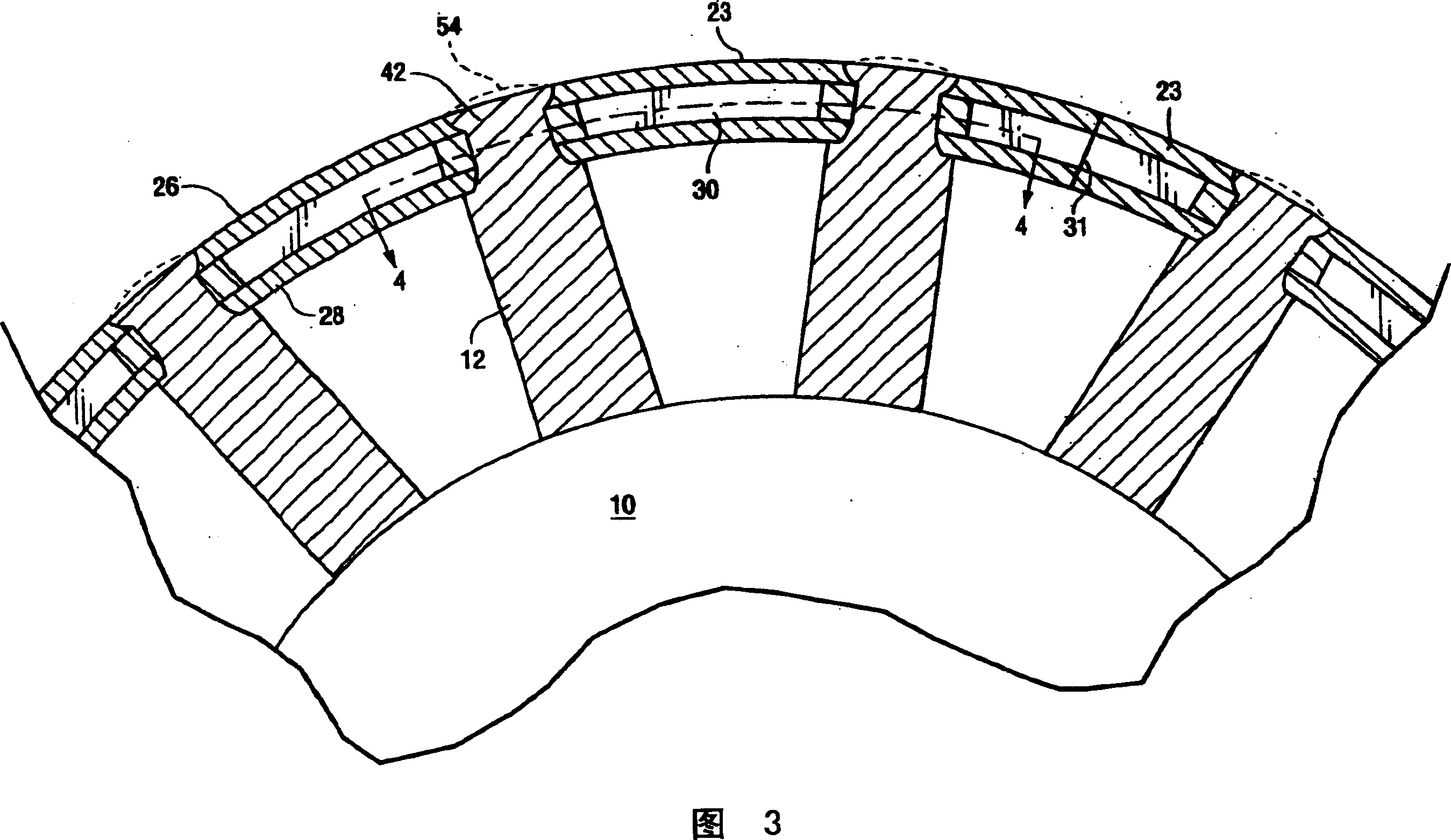
[0016] Referring now to FIG. 2 , the cover 14 includes a plurality of arcuate cover sections 23 each comprising a cover layer or element, generally indicated at 25 . As shown, the overall cover element 25 of each segment 23 includes an arcuately extending outer element 26 , an inner element 28 and an intermediate cover element 30 . The shroud elements 26, 28 and 30 extend in an arcuate manner across a plurality of blades 12, for example 4-20 blades, depending on the stage. These arcuate shroud sections are secured to tenons 32 formed...


PUM


Abstract

A bucket cover includes circumferentially disposed arcuate cover segments each having discrete arcuate inner, intermediate and outer cover elements for spanning the tips of a plurality of turbine buckets. Each segment includes circumferentially spaced radial openings through the elements for receiving the tenons at the bucket tips. The intermediate element has a cavity or recess formed between circumferentially spaced webs which define the openings through the intermediate element for weight reduction purposes. In final assembly, the tips of the tenons are automatically peened to retain the elements on the buckets and excess material is machined to provide a smooth, continuous arcuate, circumferentially extending outer surface. The cavities are bounded by the webs, forward and rear end walls and the inner and outer surfaces of the outer and inner elements, respectively.

Description

technical field [0001] The present invention relates to a multilayer blade shroud for a turbine and in particular to a multilayer blade shroud with a central perforated layer and a method of assembly thereof. Background technique [0002] Turbine rotors typically incorporate a plurality of circumferentially spaced generally radially extending airfoils or blades. Traditionally a shroud is provided at the tip of the blade, the shroud forming a 360° ring around the blade with a small gap between the outer surface of the shroud and the surrounding sleeve. [0003] There are many different constructions and methods for securing the shroud to the tip of the blade. One such known structure is the snap tenon / cover structure. In such a construction, one or more tenons projecting substantially radially from each blade pass through corresponding holes in the shroud and are preferably self-riveted along the outer surface of the shroud. This snap tenon / shroud arrangement can provide s...

Claims


Application Information

Patent Timeline
Patent Type & Authority Patents(China)
IPC IPC(8): F01D5/22F01D5/14
CPCF01D5/225Y10T29/49321F01D5/32
Inventor B·I·弗罗洛夫A·K·托尔帕迪G·L·兰德里
Owner GENERAL ELECTRIC CO
Features
  • R&D
  • Intellectual Property
  • Life Sciences
  • Materials
  • Tech Scout
  • Unparalleled Data Quality
  • Higher Quality Content
  • 60% Fewer Hallucinations
Learn More