

Audio transmission line
A conductive line and audio technology, which is applied in the field of audio conductive lines, can solve problems such as distortion, audio conductive lines not kept in the same direction, and difficult to detect audio conductive lines, etc., to achieve the effect of improving sound quality
- Summary
- Abstract
- Description
- Claims
- Application Information
AI Technical Summary
Problems solved by technology
Method used
Image

Examples
Embodiment 1
[0027] Please refer to FIG. 6A to FIG. 6D , which are drawings of Embodiment 1 of the audio conducting wire of the present invention. Although the present invention is an audio conducting wire used for audio signal transmission of a speaker, since the structure of the speaker remains unchanged and is not a feature of the present invention, the related description and drawings are omitted here.
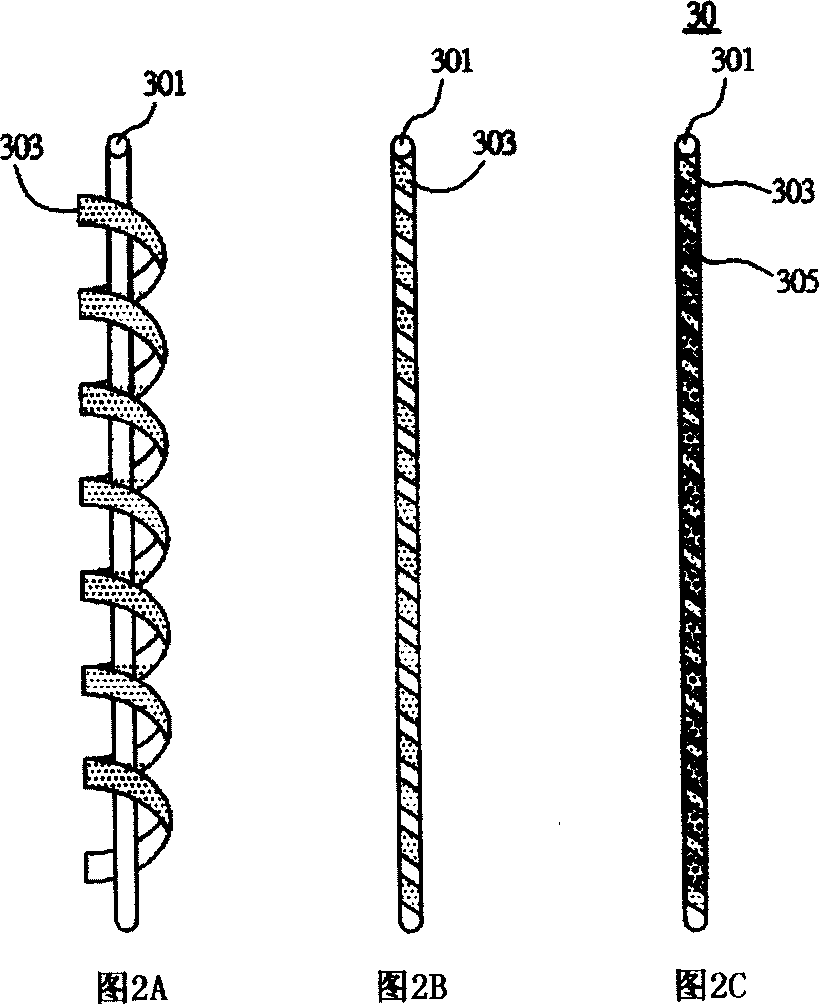
[0028] As shown in FIG. 6A , the audio conductive cable 2 in this embodiment can firstly provide a core 21 , and wrap a first conductive layer 23 around the core 21 , as shown in FIG. 6B . Next, as shown in FIG. 6C , a marking line 25 is disposed on the core 21 wrapped with the first conductive layer 23 . Finally, as shown in FIG. 6D , a second conductive layer 27 is wound on the core 21 provided with the marking line 25 . The winding direction of the second conductive layer 27 on the core 21 is the same as that of the first conductive layer 23 .
[0029] It should be noted that alth...
Embodiment 2
[0034] Fig. 7 is a drawing according to Embodiment 2 of the present invention. Wherein, in order to make the description clearer and easier to understand, the same or similar components as in Embodiment 1 are represented by the same or similar component symbols.
[0035] The biggest difference between embodiment 2 and embodiment 1 is that the winding direction of the second conductive layer 27 on the core 21 is opposite to that of the first conductive layer 23 . That is, as shown in FIG. 7, the audio conducting wire 2' is composed of a core body 21, a first conductive layer 23 wound around the core body 21, and a marking line arranged on the core body 21 wound with the first conductive layer 23. 25 and the second conductive layer 27 wound around the core 21 with the marking line 25 and exposing a plurality of marking parts 251 .
[0036] In this way, not only can the overall assembly direction of the audio conducting wire be effectively identified, avoiding rope skipping, but...
Embodiment 3
[0038] Fig. 8 is a drawing according to Embodiment 3 of the present invention. Wherein, the same or similar components as those in the above-mentioned embodiments are represented by the same or similar component symbols.
[0039] The biggest difference between Embodiment 3 and the foregoing embodiments is that the audio conducting wires at least include a first group of braided wires and a second group of braided wires.
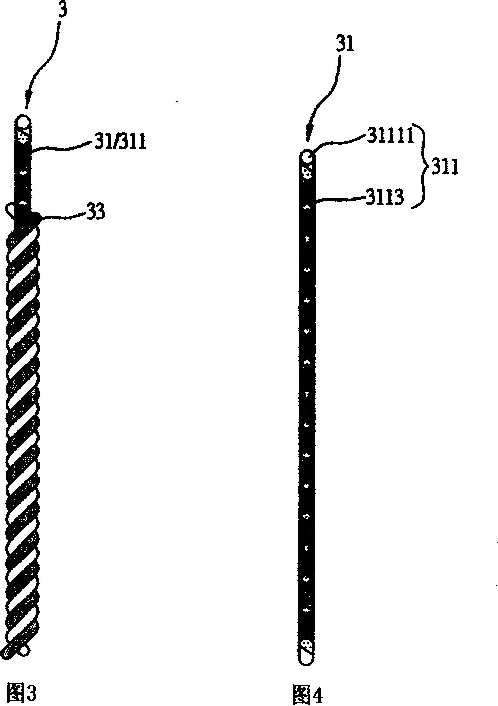
[0040] As shown in FIG. 8 , the audio conducting wire 4 of this embodiment includes a first group of braided wires 41 and a second group of braided wires 43 wound around the first group of braided wires 41 . The first group of braided wires 41 includes at least a first braided wire 411, the first braided wire 411 is composed of at least a core 4111 and at least two conductive layers 4113 wound around the core 4111 in layers, and two adjacent The winding directions of the conducting layers 4113 are interlaced. At the same time, the winding directions of the ...
PUM
 Abstract
Description
Claims
Application Information