Ball Switch
A ball switch and ball technology, applied in electrical switches, electrical components, circuits, etc., can solve the problems of difficult electroplating and manufacturing inconvenience, and achieve the effect of easy electroplating treatment and improved conduction effect.
- Summary
- Abstract
- Description
- Claims
- Application Information
AI Technical Summary
Problems solved by technology
Method used
Image
Examples
Embodiment 1
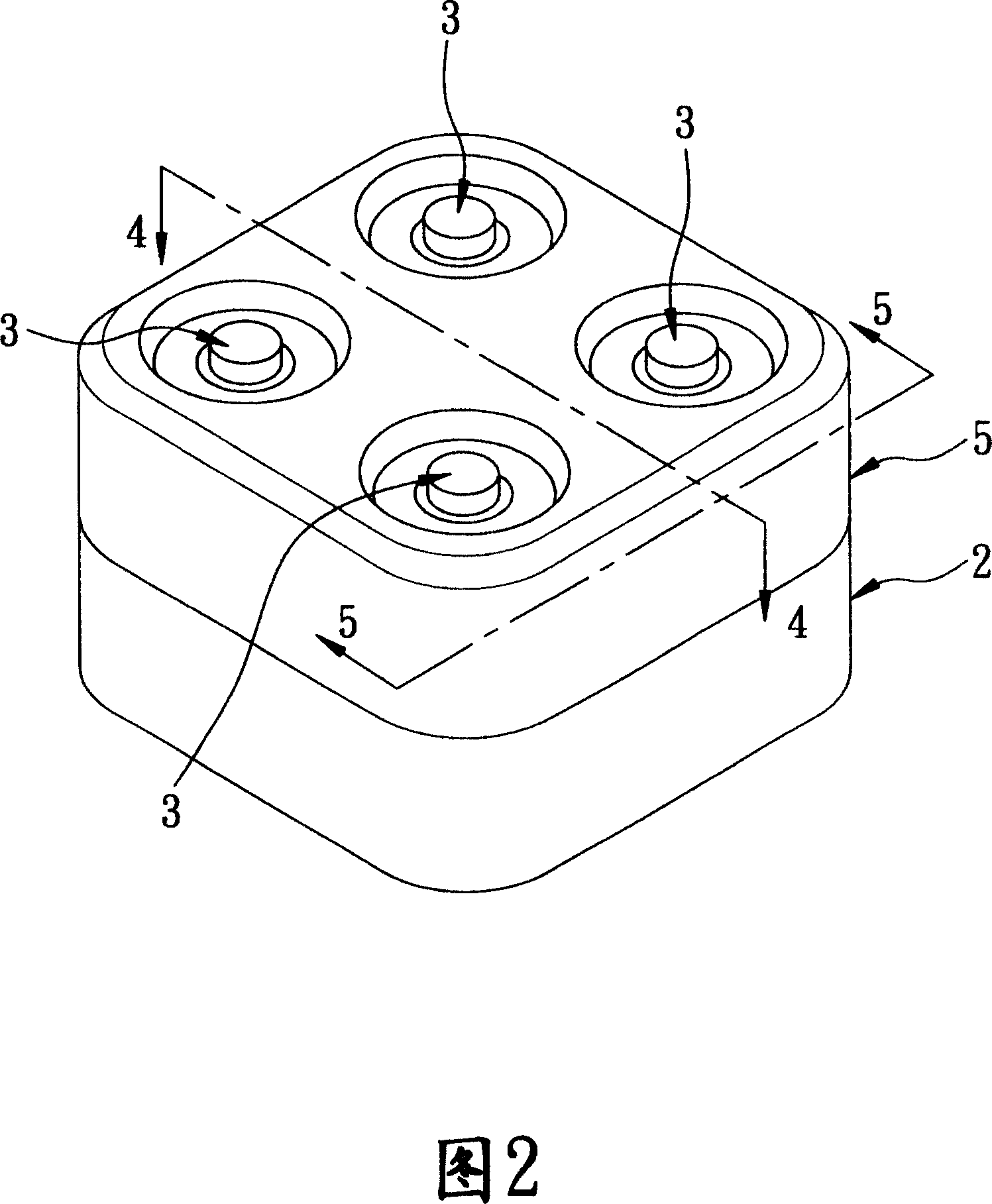
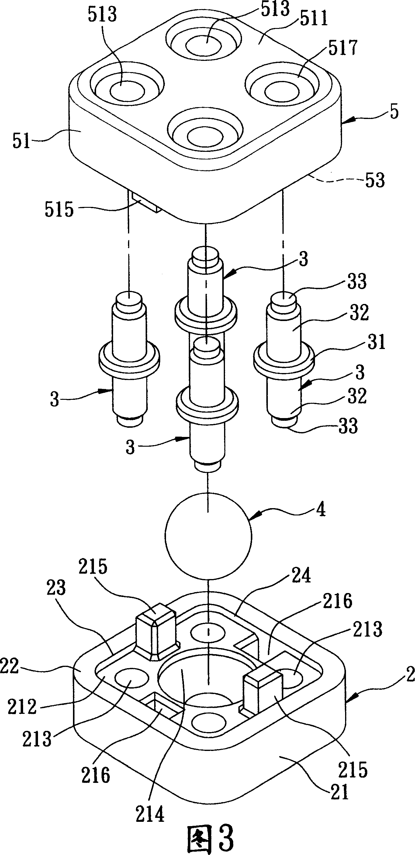
[0046] Referring to FIG. 2 and FIG. 3 , the first preferred embodiment of the ball switch of the present invention includes a housing 2 , four terminals 3 , a ball 4 , and an outer cover 5 .
[0047] Referring to Fig. 2, Fig. 3 and Fig. 4, the housing 2 is made of insulating material such as plastic, and has a base wall 21, and a peripheral wall 22 extending outward along the outer circumference of the base wall 21, and the two cooperate to define There is an accommodating space 24 with an opening 23, and the base wall 21 has four perforations 213 extending from an outer surface 211 to an inner surface 212 in an array to communicate with the accommodating space 24, and the center of the inner surface 212 A conical groove portion 214, two engaging protrusions 215 and two engaging recesses 216 located between the through holes 213 are formed on the position, and four oppositely located on the through holes 213 and formed on the outer surface 211 Guide recess 217.
[0048] The o...
Embodiment 2
[0056] Referring to Fig. 8, the second embodiment of the present invention comprises a housing 2, four terminals 3 (referring to Fig. 3), a ball 4, and an outer cover 5, the implementation concept of the second embodiment is the same as that of the first embodiment, The difference is that the grooves 214 , 514 (see FIG. 4 ) of the housing 2 and the outer cover 5 are changed into conical protrusions 218 , 518 .
[0057] In this way, when the ball switch is vertically fixed on an object 100, and is supported by the protrusion 218, the ball 4 usually contacts with the two terminals 3 no matter which angle it is inclined to. The ball switch is held in the ON state.
[0058] Referring to FIG. 9 , next, similar to the first embodiment, when the ball switch is affected by an external force and vibrates up and down, at this time, the ball 4 vibrating with the object 100 is subjected to a momentary jump, and will temporarily hang in the center of the terminal 3 , not in contact with a...
Embodiment 3
[0062] Referring to FIG. 10 , FIG. 11 and FIG. 12 , the third preferred embodiment of the present invention includes a housing 2 , four terminals 3 , a ball 4 , and an outer cover 5 .
[0063] 11 and 12, the housing 2 is made of insulating material such as plastic, and has a base wall 21, and a peripheral wall 22 extending outward along the outer circumference of the base wall 21. The two cooperate to define a An accommodating space 24 with an opening 23, the base wall 21 has several perforations 213 arranged in an array extending from an outer surface 211 toward an inner surface 212 to communicate with the accommodating space 24, and the central position of the inner surface 212 is formed There is a conical groove portion 214 .
[0064] Each terminal 3 is made of metal material, and extends from the outside to the inside from the through hole 213 into the accommodation space 24 of the housing 2, so that the terminals 3 are arranged in an array around the groove portion 214. ...
PUM
 Abstract
Description
Claims
Application Information
 - R&D
- Intellectual Property
- Life Sciences
- Materials
- Tech Scout
- Unparalleled Data Quality
- Higher Quality Content
- 60% Fewer Hallucinations
Browse by: Latest US Patents, China's latest patents, Technical Efficacy Thesaurus, Application Domain, Technology Topic, Popular Technical Reports.
© 2025 PatSnap. All rights reserved.Legal|Privacy policy|Modern Slavery Act Transparency Statement|Sitemap|About US| Contact US: help@patsnap.com


