Ball Switch

A technology of ball switches and balls, which is applied to electric switches, electrical components, circuits, etc., can solve the problems of inconvenient manufacturing and difficult electroplating, and achieve the effect of easy electroplating treatment and improved conduction effect

Inactive Publication Date: 2006-05-31
ONCQUE CORP
View PDF3 Cites 9 Cited by
  • Summary
  • Abstract
  • Description
  • Claims
  • Application Information

AI Technical Summary

Problems solved by technology

[0004] ginseng figure 1 , In addition, for the new patent case of Taiwan Patent Publication No. 537484 "Ball Switch", although the second ball 11 of the ball switch 1 has contact characteristics at all angles (360°), and is matched with a semicircular groove of the shell 12 121 and the semicircular groove portion 131 of a terminal 13 have a limiting function, so that the ball switch 5 can quickly produce a high-sensitivity switch operation as long as it is affected by external forces at any angle such as vertical direction, horizontal direction, or tilting and shaking. However, in manufacturing, in order to increase the conductive effect of the shell 11, when the metal shell 12 is subjected to electroplating treatment, the semicircular groove 121 is less likely to be electroplated, resulting in manufacturing. the inconvenience

Method used


Image

  • Ball Switch
  • Ball Switch
  • Ball Switch

Examples


Embodiment 1

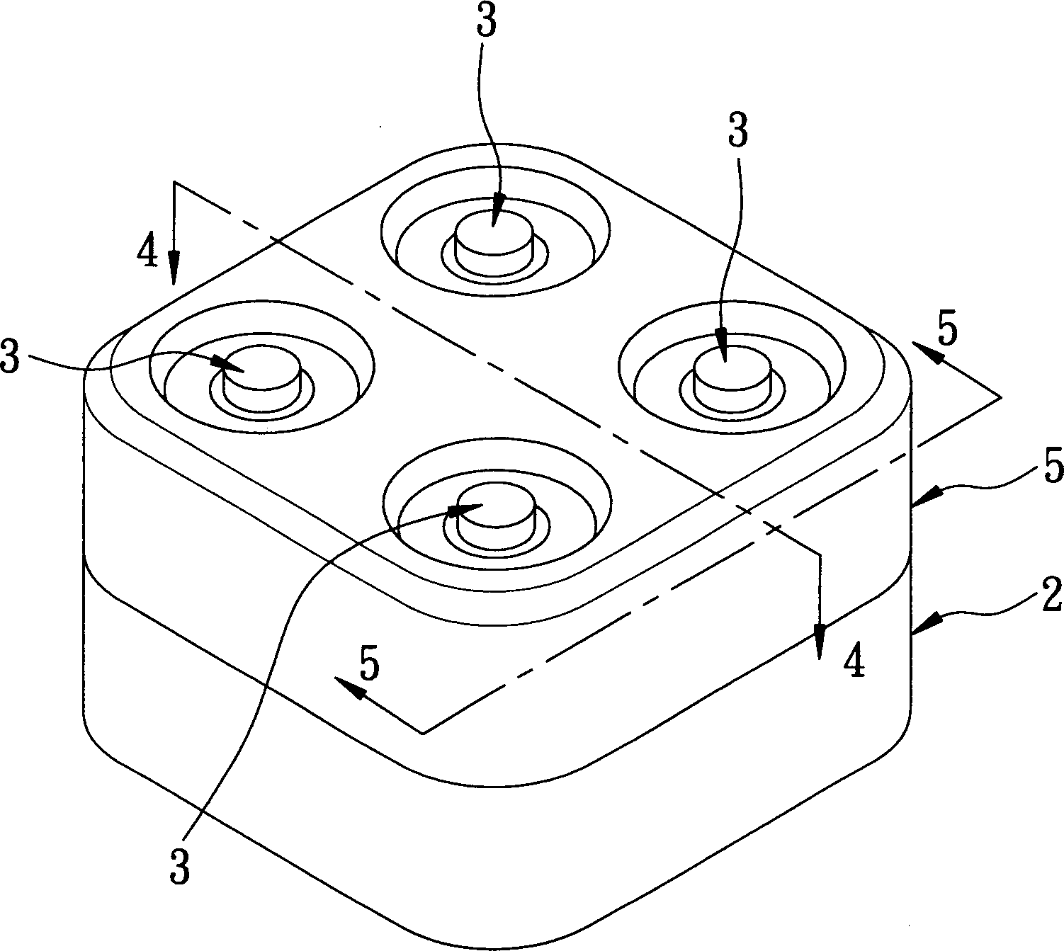
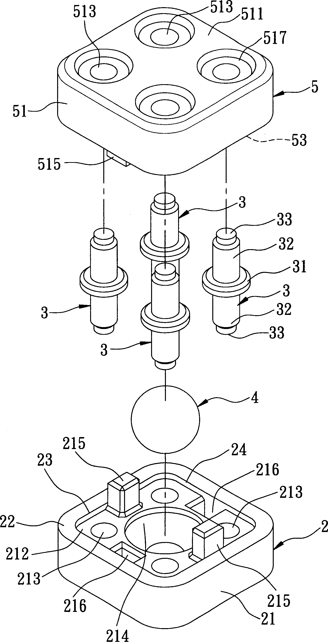
[0046] Participate figure 2 versus image 3 The first preferred embodiment of the ball switch of the present invention includes a housing 2, four terminals 3, a ball 4, and an outer cover 5.

[0047] Participate figure 2 , image 3 4, the housing 2 is made of insulating material such as plastic, and has a base wall 21 and a peripheral wall 22 extending outward along the outer circumference of the base wall 21. The two cooperate to define an open mouth The accommodating space 24 of 23, the base wall 21 has four perforations 213 arranged in an array from an outer surface 211 to an inner surface 212 extending to communicate with the accommodating space 24, and a cone shape is formed in the center of the inner surface 212 The groove portion 214, two engaging convex portions 215 and two engaging concave portions 216 located between the through holes 213, and four guide concave portions 217 located on the outer surface 211 oppositely located on the through holes 213.

[0048] The oute...

Embodiment 2

[0056] Referring to Figure 8, the second embodiment of the present invention includes a housing 2, four terminals 3 (reference image 3 ), a ball 4, and an outer cover 5. The implementation concept of the second embodiment is the same as that of the first embodiment. The only difference is that the housing 2 and the groove portions 214, 514 of the outer cover 5 (see Figure 4) Change to conical convex parts 218 and 518.

[0057] Thereby, when the ball switch is vertically fixed on an object 100 and is supported by the convex portion 218, the ball 4 is usually in contact with the two terminals 3 regardless of the angle at which it is inclined. The ball switch is kept in the ON state.

[0058] Referring to FIG. 9, next, similar to the first embodiment, when the ball switch is affected by external force and vibrates up and down, at this time, the ball 4 that vibrates with the object 100 undergoes an instant jump, and it temporarily hangs in the center of the terminals 3 , It is not in...

Embodiment 3

[0062] Participate Picture 10 , Picture 11 versus Picture 12 The third preferred embodiment of the present invention includes a housing 2, four terminals 3, a ball 4, and an outer cover 5.

[0063] Participate Picture 11 versus Picture 12 The housing 2 is made of insulating material such as plastic, and has a base wall 21 and a peripheral wall 22 extending outward along the outer peripheral ring of the base wall 21. The two cooperate to define a container with an opening 23. The base wall 21 has a plurality of perforations 213 arranged in an array and extending from an outer surface 211 to an inner surface 212 to communicate with the accommodating space 24, and a conical groove is formed in the center of the inner surface 212部214.

[0064] Each terminal 3 is made of metal and extends from the outside to the inside from the through holes 213 into the accommodating space 24 of the housing 2, so that the terminals 3 are centered on the groove portion 214 and arranged in an array...


PUM


Abstract

A ball switch is composed of a casing consisting of a base plate with an array of several through holes and a central arc recess and a peripheral wall to define an internal space with top opening, several terminals passing through said through holes on base plate, at least one ball in said internal space and an external cover for locating said terminals and closing said top opening.

Description

Technical field [0001] The invention relates to a switch, in particular to a ball switch. Background technique [0002] In order to solve the danger of general electrical appliances (such as floor lamps, desk lamps, vertical electric fans, heating fans, electric heaters, mosquito lamps and other movable electrical appliances) being shaken and falling, which may easily lead to electric wires or fires, the inventors Many ball switches have been created before, such as Taiwan Patent Publication No. 468865 "Ball Vibration Switch (3)", No. 476445 "Angle Switch (2)", and No. 537484 "Ball Switch"... and other new patent cases. [0003] In the above patents, the operating principle of the ball switches is to make the balls built in the hollow shell achieve the expected opening / closing action and purpose of use through vibration or angle tilt. Both can achieve the intended purpose of use. However, in order to ensure the action effect of the ball, the inventor will have the following brand...

Claims


Application Information

Patent Timeline
Patent Type & Authority Applications(China)
IPC IPC(8): H01H35/02
Inventor 周添铭
Owner ONCQUE CORP
Why Eureka
Try Eureka