Supercharge Your Innovation With Domain-Expert AI Agents!

Series electric splitter

A series of wire clip technology, applied in the direction of circuits, electrical components, conductive connections, etc., can solve the problem that the output side cannot be used in this way

Inactive Publication Date: 2008-02-06
PHOENIX CONTACT GMBH & CO KG
View PDF9 Cites 0 Cited by
  • Summary
  • Abstract
  • Description
  • Claims
  • Application Information

AI Technical Summary

Problems solved by technology

However, due to the arrangement of the two conductor connections in the connecting insert, it is widened so that the second, inner base clip plug-in point is covered and thus inaccessible
This has a further disadvantage: the input side, by arranging two conductor connections in the base clamp, creates two possibilities, i.e. two potentials can be connected to the electrical series clamp, while the output side cannot be used in this way, since only one can be occupied Plug position

Method used


Image

  • Series electric splitter
  • Series electric splitter
  • Series electric splitter

Examples


Embodiment Construction

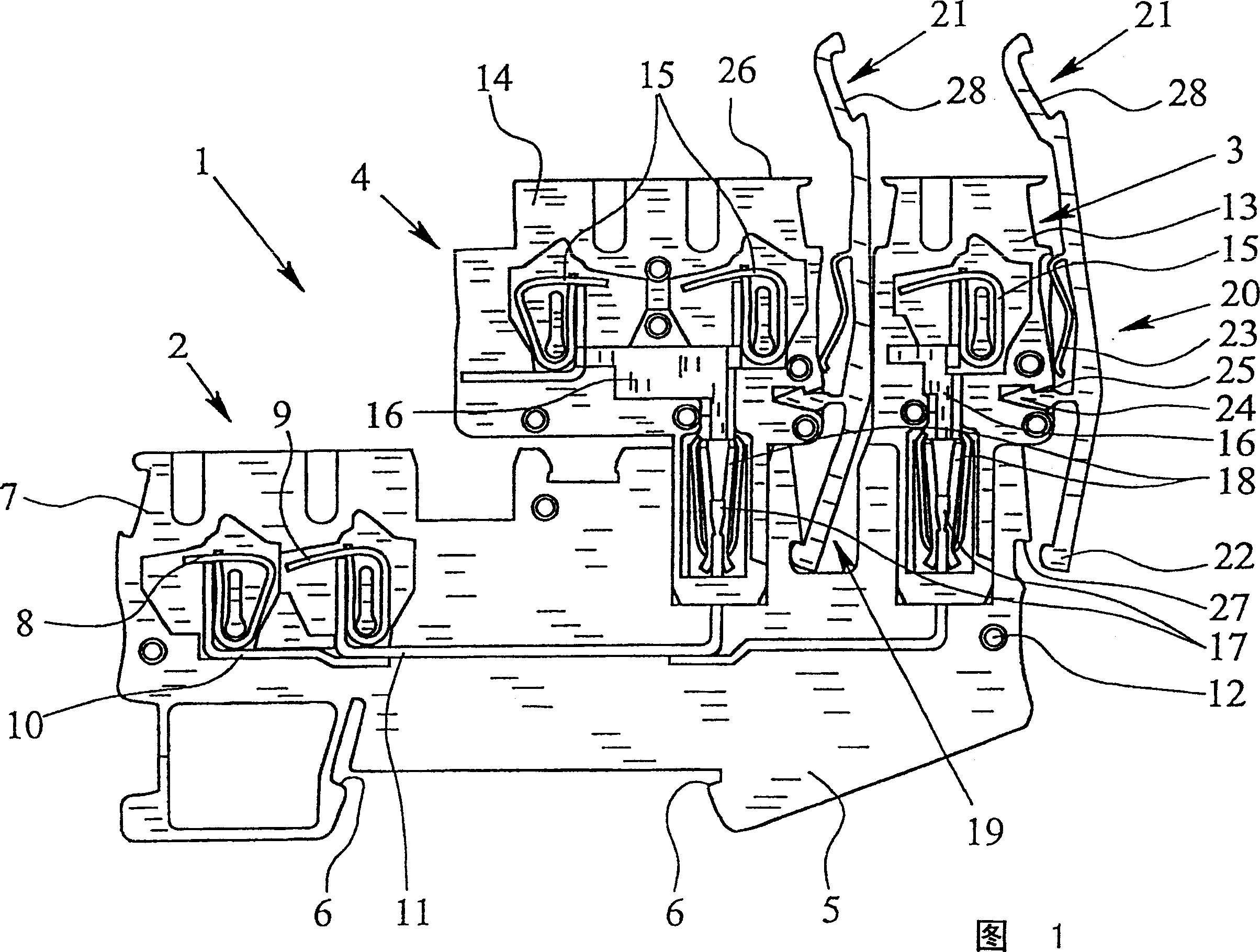
[0017] FIG. 1 shows an electrical series clamp 1 with a base clamp 2 and two connection inserts 3 , 4 . Wherein the base clip 2 constitutes a fixed part of the electric series line clamp 1, and the connecting plugs 3, 4 can be called the position variable part of the electric series line clamp 1 to a certain extent, because the connecting plugs 3, 4 can be inserted in the base clip 2. The base clip 2 can be clamped on a support rail (not shown), for which purpose corresponding clamping elements 6 are formed on the base 5 of the base clip 2 .

[0018] The base clip 2 has a clip housing 7 made of insulating material and two conductor connections 8 , 9 arranged therein. The conductor connectors 8 , 9 form tension spring clamps here, but can also form screw clamps or blade-shaped connection clamps, which are each connected to a plug-in point via current bars 10 , 11 . The disc-shaped base clamp 2 can be combined with another base clamp 2 to form a base clamp block by means of a ...


PUM


Abstract

The present invention illustrates and describes a electrical modular terminal, the base terminal (2) having a terminal housing (7) which made of insulating material, at least one terminal element (8, 9) located in it and at least two sockets which are electrically connected to the terminal element (8, 9), the plug (3, 4) having a plug housing (13, 14) which is made of insulating material, at least one terminal element (15) located therein and a plug-in contact which is electrically connected to the at least one terminal element (15), and the at least one plug (3, 4) being mechanically connected by means of a fastener to the terminal housing (7) of the base terminal (2). The at least on plug can be plugged into the two sockets of the base terminal (2), and in addition, there is mechanical attachment of the plugs (3, 4) and the base terminal (2), an interlock recess (19) being formed in the terminal housing (7) of the base terminal (2) between the two sockets for receiving the fastener an the plug (3, 4) plugged into the inner one of the two sockets for mechanically connecting it to the terminal housing (7) of the base terminal (2).

Description

technical field [0001] The invention relates to a series of electric clamps, in particular for clamping on a support rail with a base clamp and a connecting insert, wherein the base clamp has a clamp housing, at least one conductor connector arranged therein and at least two Plug-in location for the electrical connection of one or more conductor connections, wherein the connector insert has a plug housing, at least one conductor connection arranged therein and a plug contact electrically connected to the one or more conductor connections , and wherein the connecting insert is mechanically connected to the clip housing of the base clip by means of a fixing piece. Here, the clip housing and the plug housing preferably consist of insulating material. Background technique [0002] Such a kind of electric series clamp is known by DE29514711U1. Among them, the base clip is usually used to be clamped on the support rail, so that the base clip becomes a position-fixed part of the ...

Claims


Application Information

Patent Timeline
Patent Type & Authority Patents(China)
IPC IPC(8): H01R31/02H01R31/06H01R13/639H01R9/26H01R13/46H01R13/58
CPCH01R9/26H01R9/2666
Inventor O·兰格
Owner PHOENIX CONTACT GMBH & CO KG
Features
  • R&D
  • Intellectual Property
  • Life Sciences
  • Materials
  • Tech Scout
  • Unparalleled Data Quality
  • Higher Quality Content
  • 60% Fewer Hallucinations
Learn More