
Addressing and display separated driving method for driving plasma display panel

A technology of plasma display and driving method, which is applied to static indicators, instruments, identification devices, etc., and can solve the problems of relatively large differences in the number of total sustain pulses, affecting dark field brightness, and large differences in charge states.

Inactive Publication Date: 2008-02-20
四川世纪双虹显示器件份有限公司
View PDF3 Cites 0 Cited by
  • Summary
  • Abstract
  • Description
  • Claims
  • Application Information

AI Technical Summary

Problems solved by technology

Since there is a large difference in the total number of sustain pulses when displaying a bright image and a dark image, and at the same time, the time between the end of the last subfield of each field and the beginning of the first subfield of the next field is also relatively large, which means The difference in the state of the wall charge in the reset period of the first subfield between displaying a bright image and displaying a dark image is relatively large
If any image is displayed, in order to ensure the correctness of addressing, in the reset period of the first subfield, the driving waveforms of the rising ramp voltage and falling ramp voltage segments with relatively low slopes will be affected, which will affect the brightness of the dark field, thereby affecting the image quality. reduce
In order to simplify the driving circuit, whether the traditional driving method is to display a bright image or a dark image, the first subfield only uses a reset period drive waveform of the same form, while the other subfields use another reset period drive waveform. Difficult to guarantee good image quality when displaying both bright and dark images

Method used


Image

  • Addressing and display separated driving method for driving plasma display panel
  • Addressing and display separated driving method for driving plasma display panel
  • Addressing and display separated driving method for driving plasma display panel

Examples


Embodiment Construction

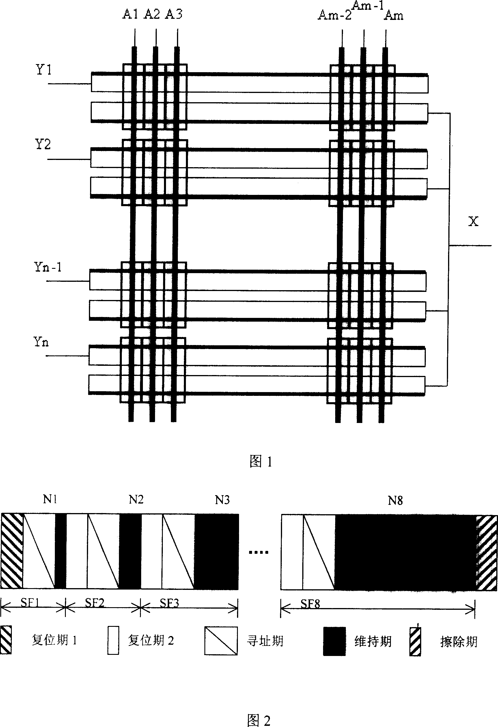
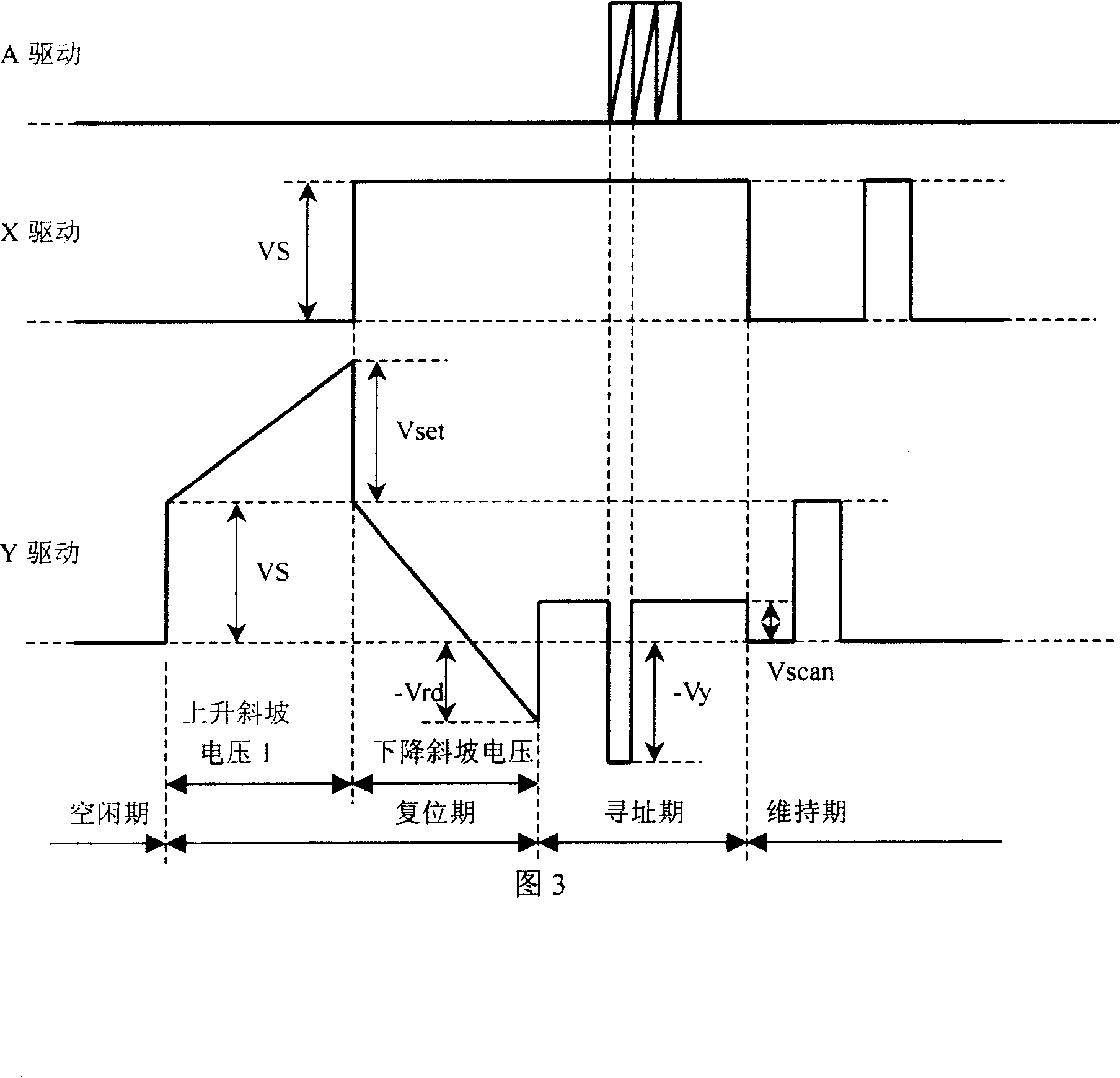
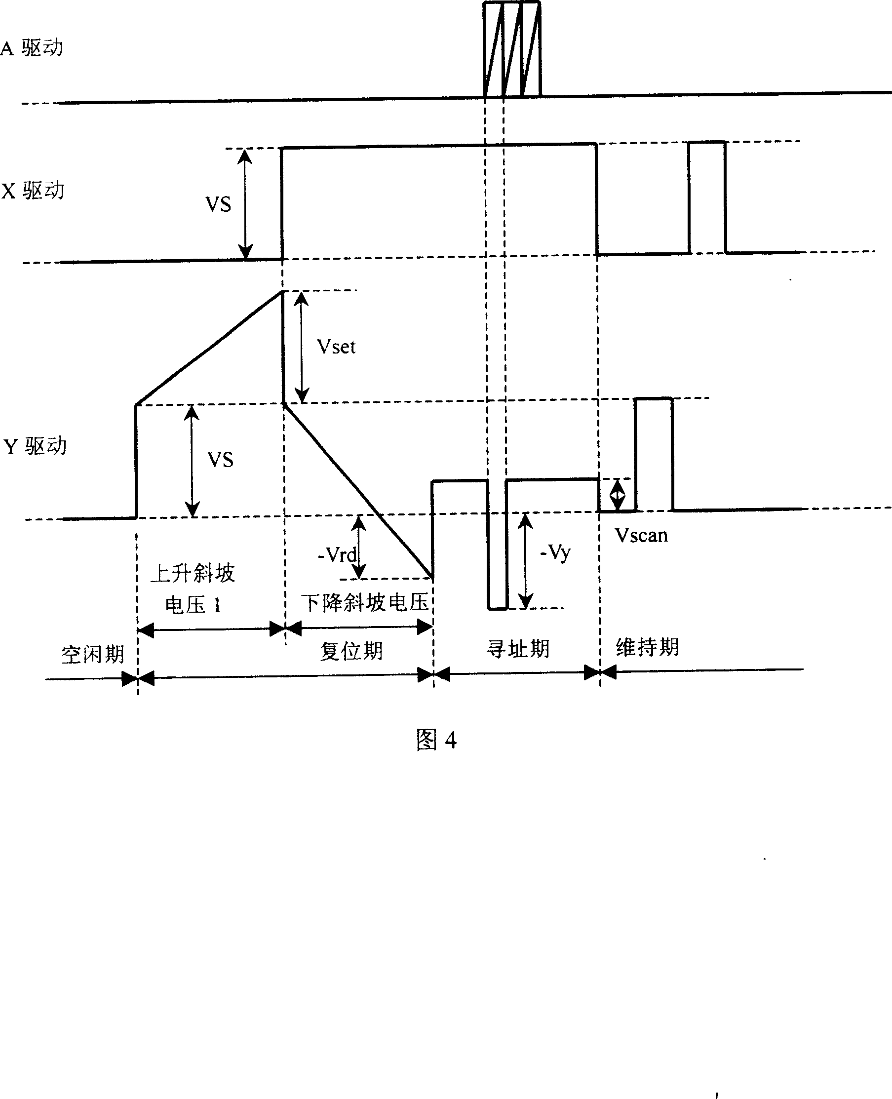
[0019] The driving method of the present invention performs display in the form of subfields. The waveform of each field is divided into several subfield waveforms and an erasing period waveform. The waveform of each subfield is composed of a reset period, an address period and a sustain period. The Y electrode reset period waveform of the first subfield has the characteristics of rising ramp voltage and falling ramp voltage, or the Y electrode reset period waveform of the first subfield has the characteristics of two rising ramp voltages and one falling ramp voltage, and The driving waveforms of the Y electrodes in the reset period of other subfields have the characteristics of falling ramp voltages. The Y electrode in the erasing period of each field waveform is characterized by a falling ramp voltage. All subfields have the same drive waveform in the address period except for the difference in the waveform in the reset period. The waveforms of the sustain period of each su...


PUM


Abstract

The invention discloses a driving method for plasma which comprises: displaying according to subfield, dividing each field wave shape into a plurality of subfield wave shape and a erasing period wave shape ; each subfield wave shape includes resetting period, addressing period and maintaining period, employing different Y electrode resetting period driving wave shape for displaying bright images or dark images; erasing period Y electrode of each field wave shape is descending oblique wave voltage and all subfields have the same addressing period driving wave shape; each subfield maintaining period has the same wave shape, and has different amount of maintaining pulse according to each subfield weight.

Description

technical field [0001] The invention belongs to the technical field of gas discharge, and relates to a driving method of a plasma display, in particular to a method for separately addressing and displaying a three-electrode surface discharge plasma display. Background technique [0002] The Plasma Display Panel (Plasma Display Panel) that uses discharge light has become one of the most competitive products in the display device market with large screen and thin thickness because of its wide viewing angle, large screen, high brightness, and thin thickness. At present, the plasma display needs to be further improved in terms of improving image quality, reducing power consumption, and reducing costs. [0003] The three-electrode surface discharge plasma display has scan electrodes (Y1, Y2, ...Yn), sustain electrodes (X) and address electrodes (A1, A2, ...Am) arranged orthogonally to the scan electrodes and the sustain electrodes. A display unit that can represent red, green, o...

Claims


Application Information

Patent Timeline
Patent Type & Authority Patents(China)
IPC IPC(8): G09G3/28G09G3/288G09G3/20H01J17/49G09F9/313G09G3/292G09G3/298
Inventor 符赞宣
Owner 四川世纪双虹显示器件份有限公司
Learn More