Fastening conductive mechanism convenient to operate and used for assembling aluminum electrolysis anode carbon block

An aluminum electrolytic anode and carbon block technology, which is applied in the field of convenient operation and fastening of conductive mechanisms, can solve the problems of inoperability, difficulty in maintaining regular shape, and reduced contact area, and achieves small occupied space, simple structure, and reduced occupied space. Effect

Pending Publication Date: 2022-05-17
贵州和泰达科技有限公司
View PDF12 Cites 0 Cited by
  • Summary
  • Abstract
  • Description
  • Claims
  • Application Information

AI Technical Summary

Problems solved by technology

Moreover, the shape of this whole board will be deformed and warped when thermal expansion occurs, resulting in a greatly reduced contact area.
[0022] Patent CN206089844U discloses a connection structure between an anode carbon block and a steel claw. It is recorded in the patent that "the steel claw is connected to the connecting groove to fix the anode", and the shape of the steel claw and the specific connection operation mechanism are not described. From the schematic diagram, The connection groove is an "L"-shaped hole, and it is impossible to understand what kind of steel claws can be put into the hole without destroying the connection groove, and how to maintain close contact and conduct electricity after being heated
The auxiliary hook on its structure does not specify what material it is. From the perspective of common sense, it should be a metal material that can maintain strength in a high-temperature environment. This will contact high-temperature electrolyte solution and aluminum liquid, causing aluminum liquid pollution.
"The steel claw is connected to the connecting groove to fix the anode." It does not explain the specific connection operation mechanism of the steel claw and the carbon block. From the schematic diagram, the connection operation mechanism will be covered by the hardened high-temperature electrolyte layer, which is impossible. operational
In addition, "the steel claw is connected to the connecting groove to fix the anode", without specifying the specific connection operation mechanism of the steel claw and the carbon block. From the schematic diagram, the size of the connecting parts is very small, which is far from the traditional steel claw connection. The conductive area, and the conductive contact pressure only depends on the weight of the carbon block, which cannot meet the actual production conductive needs
The shape of the carbon block described has complex and special-shaped structures such as numerous grooves and holes. It cannot be demoulded during the production of carbon block molding, and it is difficult to clean and maintain a regular shape after high-temperature pre-baking.
[0023] Patent CN208933499U discloses an anode carbon block clamp arm. The mechanism described in this patent completely changes the traditional aluminum guide rod hanging carbon block structure, but sets frames, clamp arms and other structures around the carbon block. This structure Impossible to use in existing electrolyzers, the entire structure of the electrolyzer and even the plane layout of the electrolytic workshop must be greatly adjusted

Method used


Image

  • Fastening conductive mechanism convenient to operate and used for assembling aluminum electrolysis anode carbon block
  • Fastening conductive mechanism convenient to operate and used for assembling aluminum electrolysis anode carbon block
  • Fastening conductive mechanism convenient to operate and used for assembling aluminum electrolysis anode carbon block

Examples


Embodiment

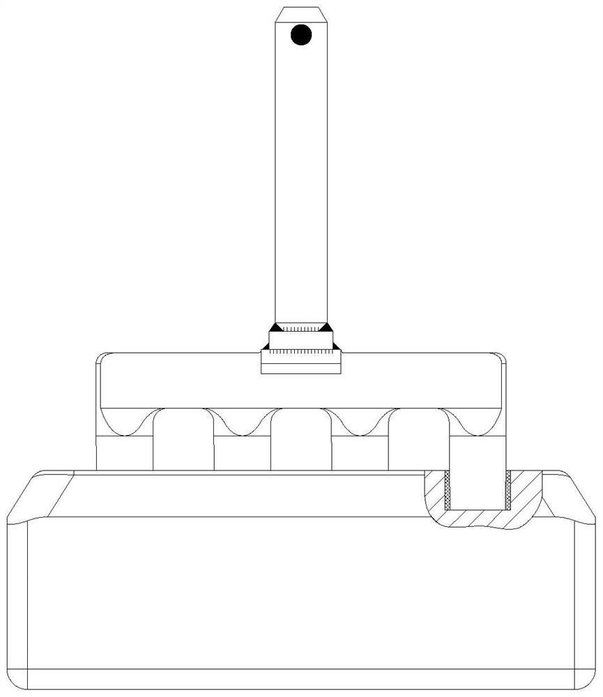
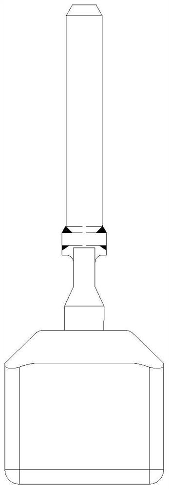
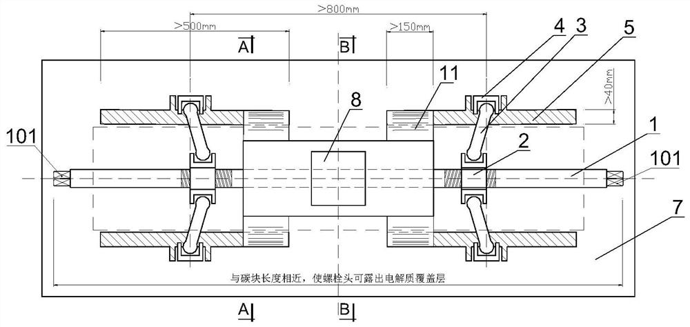
[0059] combine image 3 , Figure 4 , Figure 6 as well as Figure 8 As shown, a convenient operation fastening conductive mechanism for the assembly of aluminum electrolytic anode carbon blocks provided by the present invention includes an electrolyte shield 7, an aluminum guide rod 8, a threaded screw 1, and a conductive voltage plate 5; the aluminum guide The rod 8 is arranged on the top of the electrolyte guard plate 7; the bottom of the electrolyte guard plate 7 is provided with a bar-shaped groove 701, and the bar-shaped groove 701 is used to accommodate the clamping part of the anode carbon block 12; in the bar-shaped groove The two side walls of 701 are respectively provided with pressure plate holes 703; the conductive voltage plate 5 is arranged at the position of the pressure plate hole 703; the conductive voltage plate 5 and the electrolyte guard plate 7 are electrically connected through a conductor 11; The threaded screw 1 is arranged on the electrolyte shield...


PUM

PropertyMeasurementUnit
thicknessaaaaaaaaaa
lengthaaaaaaaaaa
widthaaaaaaaaaa

Abstract

A fastening conductive mechanism convenient to operate and used for assembling an aluminum electrolysis anode carbon block comprises an electrolyte protection plate, an aluminum guide rod, a threaded screw rod and a conductive pressing plate. The aluminum guide rod is arranged at the top of the electrolyte protection plate; a strip-shaped groove is formed in the bottom of the electrolyte protection plate and is used for accommodating a clamping part of the anode carbon block; pressing plate holes are respectively formed in two side walls of the strip-shaped groove; the conductive pressing plate is arranged at the position of the pressing plate hole; the conductive pressing plate is conductively connected with the electrolyte protection plate through a conductor; the threaded screw rod is arranged on the electrolyte protection plate, and a threaded sliding sleeve is arranged on the threaded screw rod; a connecting rod structure is arranged on the electrolyte protection plate, one end of the connecting rod structure is connected with the threaded sliding sleeve, and the other end of the connecting rod structure is connected with the conductive pressing plate; when the threaded screw rotates forwards or reversely, the threaded sliding sleeve is driven to move in the axial direction of the threaded screw, and the conductive pressing plate is driven to press or loosen the clamping part of the anode carbon block through the connecting rod structure.

Description

technical field [0001] The invention relates to the technical field of carbon block clamping tools in aluminum electrolysis, in particular to a conveniently operated fastening conductive mechanism for assembling anode carbon blocks in aluminum electrolysis. Background technique [0002] At present, the metal aluminum smelting all over the world adopts the electrolysis process. In the electrolytic cell, dozens of groups of anodes suspended side by side and dozens of groups of cathodes built on the bottom of the cell are used to electrolyze the alumina. The oxygen in the alumina and The anode carbon block reacts to generate carbon dioxide and carbon monoxide, and the remaining pure aluminum is left in the electrolytic cell to complete the smelting process. [0003] Each anode component of the current aluminum electrolytic cell (such as figure 1 and figure 2 shown) are composed of upper aluminum guide rod, middle steel beam and steel claw, and lower carbon block. The aluminu...

Claims


Application Information

Patent Timeline
Patent Type & Authority Applications(China)
IPC IPC(8): C25C3/12
CPCC25C3/125
Inventor 祁晓牧
Owner 贵州和泰达科技有限公司
Why Eureka
Try Eureka