
Method and apparatus to sort particles flowing from verticle grinder

一种颗粒、颗粒流的技术,应用在分离方法、弥散粒子分离、化学仪器和方法等方向,能够解决增加压力损失、减小分选效率等问题,达到避免干扰的效果

Inactive Publication Date: 2008-03-26
KAUTEX TEXTRON GMBH & CO KG
View PDF8 Cites 0 Cited by
  • Summary
  • Abstract
  • Description
  • Claims
  • Application Information

AI Technical Summary

Problems solved by technology

[0009] All of the above sorter designs involve interference between the different streams and, therefore, are susceptible to increased pressure loss and reduced sorting efficiency

Method used


Image

  • Method and apparatus to sort particles flowing from verticle grinder
  • Method and apparatus to sort particles flowing from verticle grinder
  • Method and apparatus to sort particles flowing from verticle grinder

Examples


Embodiment Construction

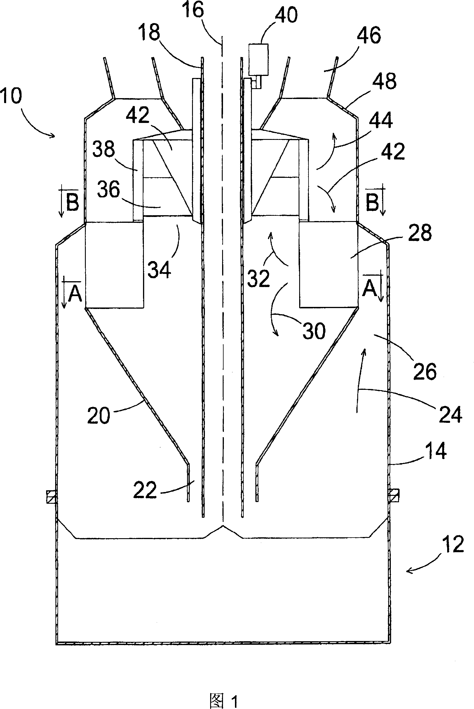
[0031] FIG. 1 schematically shows a classifier 10 connected to a vertical spindle mill 12 . Sorter 10 includes a generally cylindrical housing 14 having a vertical axis 16 . At the shaft 16 is often arranged a feed pipe 18 for guiding the raw material to the center of the mill 12 to be ground as it travels towards the outer edge of the mill 12 .

[0032] Inside the outer shell 14 is arranged a conical inner shell 20 which has a central outlet 22 at the bottom for the outflow of the separated coarse particles from the classifier 10 to the mill 12 for regrinding. The outlet 22 may include a hinge structure (not shown) to prevent gas from flowing upwardly into the inner housing 20 through the opening 22 .

[0033] An annular gas and particle flow 24 flows upwardly from the mill 12 through a channel 26 formed between the outer shell 14 and the inner shell 20 . The flow 24 is directed to the inner shell 20 through an inlet and outlet formed by an annulus 28 comprising an angular ...


PUM


Abstract

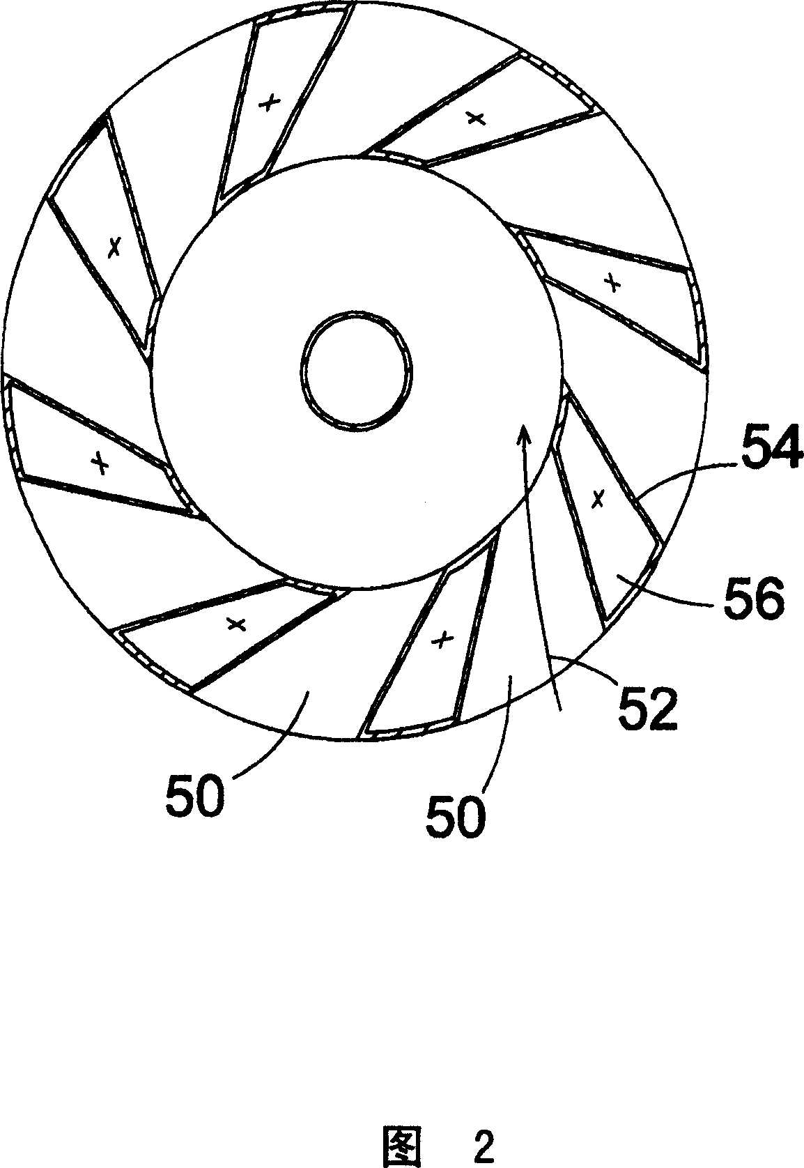
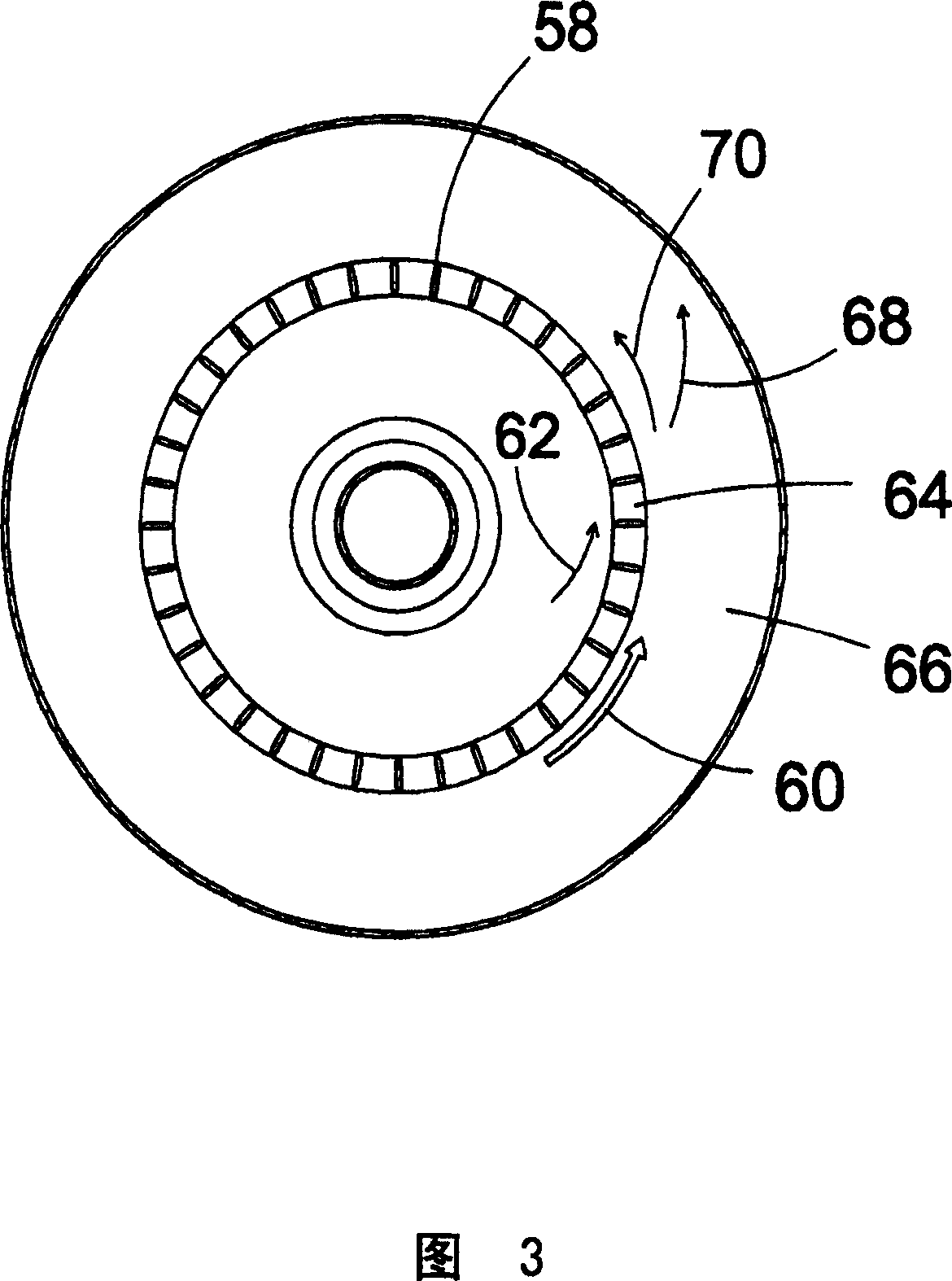
A classifier for separating coarse particles from a stream of gas and particles discharged from a vertical mill includes a generally cylindrical outer casing, an inner casing, a ring, and a wheel. The outer casing has a vertical axis and a vertically oriented sidewall disposed on the mill. The inner casing is arranged within the outer casing, providing an annular passageway between the inner casing and the sidewall through which the stream of gas and particles flows upwardly. The ring is supported about the axis and includes a plurality of circumferentially-spaced static vanes forming angled ports for imparting rotational motion to the stream of gas and particles flowing through the ports for centrifugally separating a portion of coarse particles, thereby producing a remaining stream of gas and particles. The wheel is supported for rotation about the vertical axis and includes a plurality of circumferentially-spaced radially extending blades for accelerating the rotational motion of the remaining stream for separating another portion of coarse particles, thereby producing a final stream of gas and particles to be discharged from the classifier. The portion of coarse particles and the other portion of coarse particles are discharged from the classifier through an outlet for separated particles.

Description

technical field [0001] The present invention relates to a method and an apparatus for separating coarse particles from a gas stream exiting a vertical mill and a mixture of coarse and fine particles. More specifically, the present invention relates to a dynamic particle sorter for pneumatically separating coarse particles from a gas stream and particles exiting a vertical mill, and a separation method for a dynamic particle sorter. Background technique [0002] Typically a dynamic particle separator includes a rotating impeller. The purpose of such a particle classifier is to remove oversized particles from the primary stream (eg, gas flow) without removing many fine particles. By combining a set of stationary vanes and a set of rotating vanes in the classifier, the sharpness of the particle size distribution in the output stream of the dynamic classifier is generally increased. [0003] Particle separators are often used in combination with vertical mills that grind coars...

Claims


Application Information

Patent Timeline
Patent Type & Authority Patents(China)
IPC IPC(8): B02C23/08B01D45/12B02C15/00B02C23/18B02C23/32
CPCB02C23/32B02C2015/002
Inventor F·埃辛格
Owner KAUTEX TEXTRON GMBH & CO KG
Learn More