Combined gas-liquid separator

A technology of gas-liquid separator and liquid separator, which is applied in the field of combined gas-liquid separator, can solve the problem of insufficient separation efficiency, achieve the effect of strengthening the gravity separation process and improving separation efficiency

Inactive Publication Date: 2013-05-01
西安思瑞迪精馏工程有限公司
View PDF8 Cites 10 Cited by
  • Summary
  • Abstract
  • Description
  • Claims
  • Application Information

AI Technical Summary

Problems solved by technology

[0003] With the improvement of separation and environmental protection requirements, the above-mentioned gas-liquid separator has exposed the disadvantage that its separation ef

Method used


Image

  • Combined gas-liquid separator
  • Combined gas-liquid separator
  • Combined gas-liquid separator

Examples


Embodiment 1

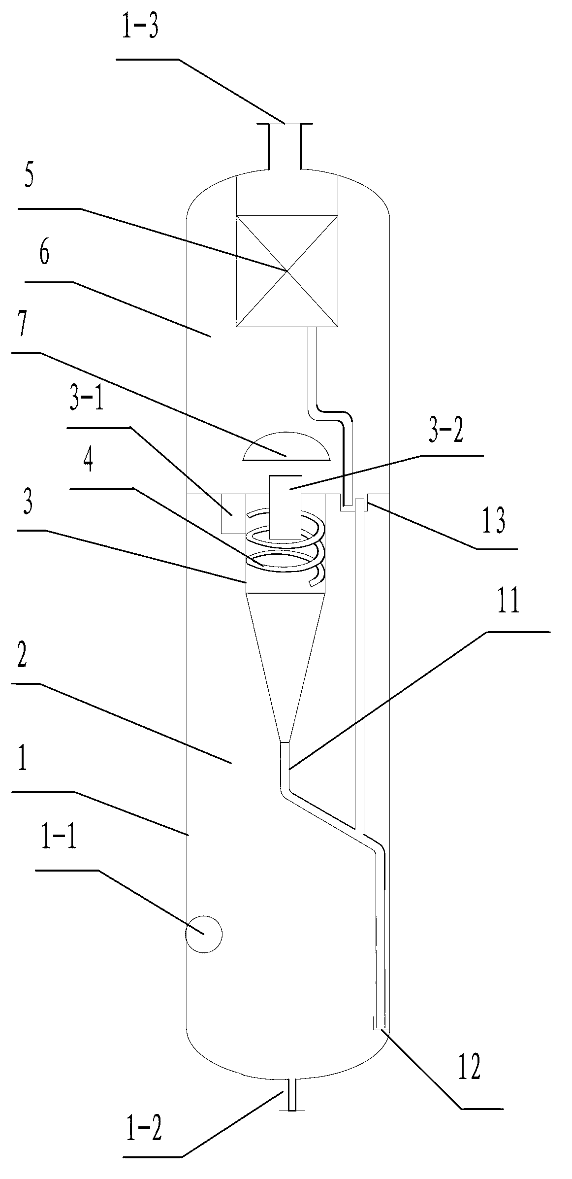
[0022] see figure 1 , which has a housing (1) with a gas phase outlet (1-3) at the top of the housing, a liquid phase outlet (1-2) and a gas-liquid mixed phase at the lower part of the housing Inlet (1-1); a cyclone gas-liquid separator is provided in the housing (1), and the cyclone gas-liquid separator consists of a cyclone separator (3) and a cyclone cylinder located in the cyclone separator The spiral vane deflector (4) inside the cyclone gas-liquid separator separates the upper chamber (6) and the lower chamber (2) of the shell cavity, and the air inlet of the cyclone gas-liquid separator (3- 1) It communicates with the lower chamber (2), and the air outlet (3-2) of the cyclone gas-liquid separator communicates with the upper chamber (6), and there is a collision at the air outlet (3-2) deflector baffle (7); a mist eliminator (5) is provided in the upper chamber (2), and the mist eliminator can be an ordinary wire mesh eliminator or a baffle plate eliminator, but It is...

Embodiment 2

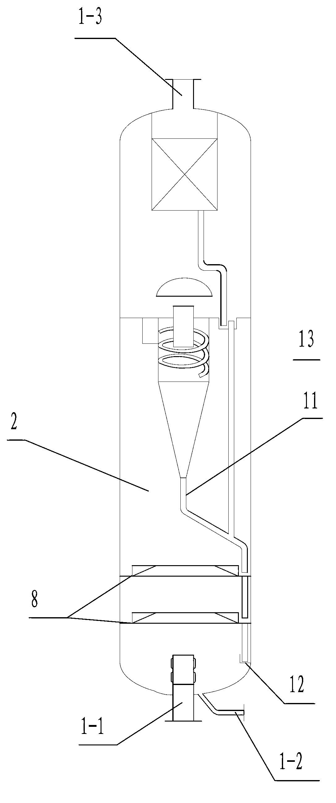
[0025] see figure 2 , the structure of this example is basically the same as that of Example 1, the difference is that a second-layer swirl plate (8) is added in the lower chamber (2), and the gas-liquid mixed phase inlet (1-1) adopts the lower Import, other structures are identical with embodiment 1. The intake air enters the shell (1) from the gas-liquid mixed phase inlet (1-1), passes through the double-layer swirl plate and is transformed into a rotating upward airflow, and the liquid droplets entrained in the airflow are thrown towards the inner wall of the shell at a certain elevation angle, and then Descends along the inner wall of the shell, enters the first liquid seal plate (12) through the guide tube, then overflows and descends to the bottom of the shell, and is discharged from the liquid phase outlet (1-2); the rotating and rising air flow enters the cyclone gas-liquid Separator, following process is identical with embodiment 1. In this example, another cyclone...

Embodiment 3

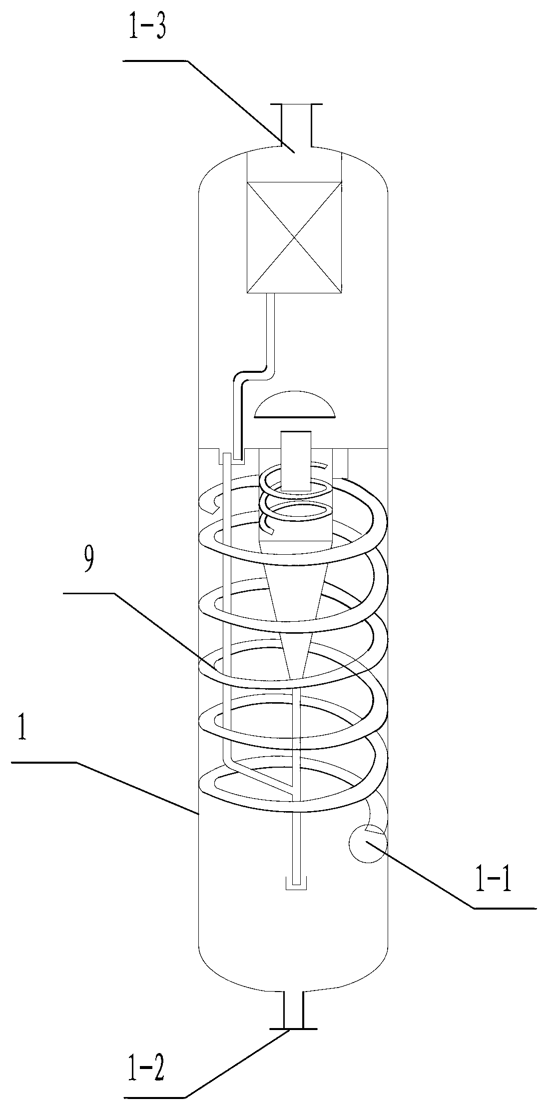
[0027] see image 3 , The structure of this example is basically the same as that of Example 1, the difference is that a second spiral deflector (9) is added in the lower chamber (2), and other structures are the same as those of Example 1. The intake air enters the casing (1) from the gas-liquid mixed phase inlet (1-1), and makes a spiral upward movement along the second spiral deflector (9), and the liquid drops in the second spiral deflector (9) ) and the inner wall of the shell coalesce and fall, and are discharged from the liquid phase separation outlet (1-2); the rotating rising airflow enters the cyclone gas-liquid separator, and the following process is the same as that of Example 1. In this example, a spiral diversion separation is added before the cyclone gas-liquid separation to further improve the separation efficiency.

[0028] The above three embodiments are used for gas-liquid separation with a small amount of liquid phase in the gas phase.


PUM


Abstract

The invention discloses a combined gas-liquid separator comprising a shell, wherein a cyclone gas-liquid separator is arranged in the shell; and the cyclone gas-liquid separator is composed of a cyclone separator and a spiral sheet guide plate which is arranged in the cyclone of the cyclone separator. The cyclone gas-liquid separator combines a cyclone separation function and a spiral guide separation function; the separation efficiency of the cyclone gas-liquid separator is higher than the centrifugal separation efficiency of a two-layered swirl plate, as well as higher than the single spiral sheet guide separation efficiency or single collision separation efficiency. Meanwhile, a collision guide flow baffle is arranged at an air outlet of the cyclone gas-liquid separator, and is combined with a swirling mist eliminator, so that the separation efficiency is greatly improved. A further improvement of the combined gas-liquid separator is that a swirl plate, a second spiral sheet guide plate or a spraying overflow tray is also added at the lower part of the shell, so that the combined gas-liquid separator is also additionally provided with a primary gas-liquid separation function based on the separation functions, and the separation efficiency is further improved.

Description

technical field [0001] The invention relates to a gas-liquid separator, in particular to a combined gas-liquid separator. Background technique [0002] At present, most of the gas-liquid separators used in the chemical industry are single-stage separators, and there are also two-stage separators. The first-stage separation of the two-stage separator is a gravity separator improved by gravity first (such as: swirl plate, Collision deflector baffle or spiral plate deflector, etc.) to separate most of the droplets, and the second stage separation is to separate the remaining droplets through ordinary wire mesh demister or baffle demister. For example: At present, an oil-gas separator that has been used in industry, such as Figure 5 As shown, it is a down-entry structure, mainly composed of a casing (100), two layers of swirl plates (200) and a wire mesh eliminator (300) arranged in the casing. Oil and gas enter the casing (100) from the lower inlet (100-1), pass through the s...

Claims


Application Information

Patent Timeline
IPC IPC(8): B01D50/00
Inventor 褚雅志褚颖娟王领刘燕付亚玮王瑞杜蕾
Owner 西安思瑞迪精馏工程有限公司
Why Eureka
Try Eureka