System and Method for Improving the Separation of Entrained Solids from a Solution Within a Centrifuge

a centrifuge and solid separation technology, applied in the direction of centrifuges, well accessories, separation processes, etc., can solve the problems of fluid dilution, increase in the total amount of solids that may be removed from the supporting solution, increase in the remaining volume of supporting fluid, etc., to enhance the centrifugal enhance the separation of entrained solids

Inactive Publication Date: 2011-01-13
FP MARANGONI INC
View PDF14 Cites 6 Cited by
  • Summary
  • Abstract
  • Description
  • Claims
  • Application Information

AI Technical Summary

Benefits of technology

[0009]In accordance with a first embodiment, the invention provides a centrifuge for enhancing the separation of entrained solids within a solution comprising: a rotatable bowl for supporting a volume of fluid, the rotatable bowl operatively connected to an input port for introducing fluid to the rotatable bowl, a fluid discharge port for removing fluid from the rotatable bowl and a solids discharge port for removing solids from the rotatable bowl; a gas injection system operatively connected to the rotatable bowl for introducing a gas to the rotatable bowl and dispersing the gas within the rotatable bowl and liquid, the gas injection system being operable to adjust the density and viscosity of the fluid to enhance the centrifugal separation of the entrained solids from the solution during rotation of the rotatable bowl.

Problems solved by technology

Unfortunately, while this method may result in an increase in the total amount of solids that may be removed from the supporting solution, the increase in the remaining volume of supporting fluid may or may not be beneficial.
A key problem in the operation of centrifuges with drilling fluids is the effect of fluid dilution.
However, this will result in an overall volume increase of the fluid which may then require additional treatment to re-adjust the viscosity to a desired degree.
As drilling fluids, are highly expensive, there has been a need for a system and method of enhancing the removal of fine solids from drilling solutions without permanently affecting the viscosity or volume of the drilling fluid.
A review of the prior art reveals that such a system has not been developed in the past.

Method used


Image

  • System and Method for Improving the Separation of Entrained Solids from a Solution Within a Centrifuge
  • System and Method for Improving the Separation of Entrained Solids from a Solution Within a Centrifuge
  • System and Method for Improving the Separation of Entrained Solids from a Solution Within a Centrifuge

Examples


Embodiment Construction

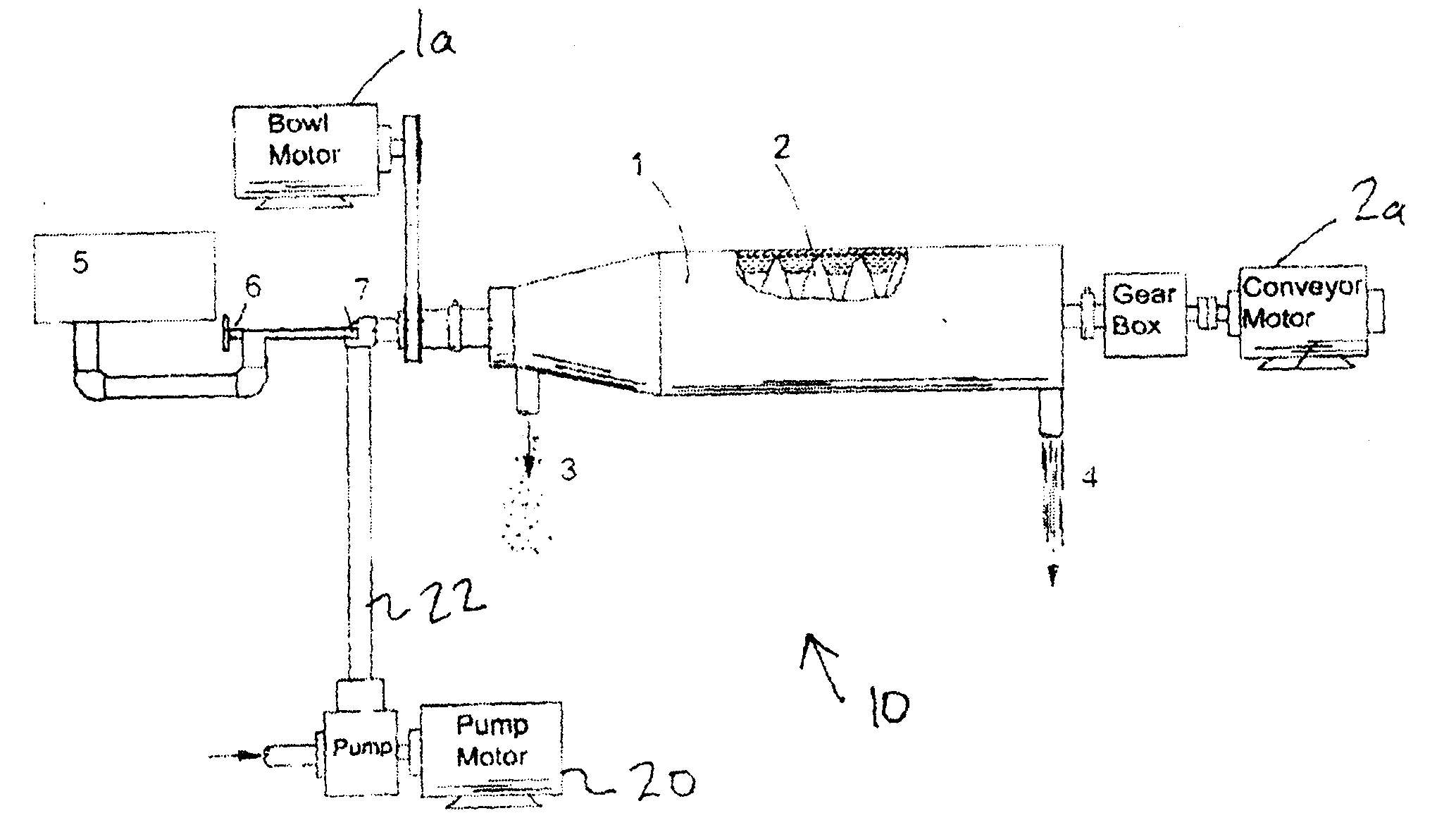
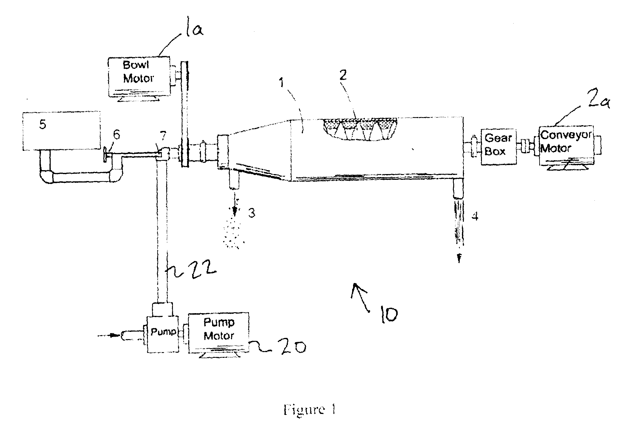
[0013]With reference to the figures, a centrifuge system 10 is described enabling improved separation of fine solids from a viscous supporting solution. The system is particularly effective in removing suspended fine solids from a drilling solution as used in the drilling industry. The system is described in the context of separating fine solids from a drilling solution (or drilling mud) although it is understood that the principles described herein may be applied to other centrifuge systems and solutions where it is desired to improve the efficiency of separation.

[0014]The centrifuge system 10 generally includes a bowl 1 for supporting a volume of drilling fluid and imparting a centrifugal force on the drilling fluid within the bowl, a screw conveyor 2 (with gear box and motor 2a) for moving separated fines to discharge port 3 and discharge port 4 for removing the drilling fluid from the bowl. The system also includes a pump motor and pump 20 for pumping drilling fluid into the bow...


PUM

PropertyMeasurementUnit
volumeaaaaaaaaaa
densityaaaaaaaaaa
viscosityaaaaaaaaaa

Abstract

The present invention describes a centrifuge system and method for improving the separation of entrained solids from a solution. The system and method introduces compressed gas to a fluid containing entrained solids to reduce the density and viscosity of the fluid to promote the settling of particles within the solution.

Description

FIELD OF THE INVENTION[0001]The present invention describes a centrifuge system and method for improving the separation of entrained solids from a solution. The system and method introduces compressed gas to a fluid containing entrained solids to reduce the density and viscosity of the fluid to promote the settling of particles within the solution.BACKGROUND OF THE INVENTION[0002]It is known that centrifuges are effective in the removal of fine solids from solution. It is also known that dilution of a supporting fluid containing fine solids with a clean supporting fluid of the same type (i.e. free of fine solids) can be used reduce the viscosity and density of the fluid and improve the operational efficiency of the centrifuge. That is, by reducing the fluid viscosity, a higher proportion of fine solids may be removed from the supporting fluid. Unfortunately, while this method may result in an increase in the total amount of solids that may be removed from the supporting solution, th...

Claims


Application Information

Patent Timeline
Patent Type & Authority Applications(United States)
IPC IPC(8): B01D21/26B04B15/00B04B11/00B04B1/00
CPCB04B1/20B04B15/00B01D21/32B01D21/262B01D2221/04E21B21/065
Inventor POMERLEAU, DANIEL GUY
Owner FP MARANGONI INC
Why Eureka
Try Eureka