Maximum differential flow brake device for preventing voltage transformer differential protection unwanted operation

A differential protection and transformer technology, applied in emergency protection circuit devices, electrical components, etc., can solve the problems of transformer differential protection misoperation, inability to perform reliable braking, large differential unbalanced current, etc.

Inactive Publication Date: 2008-03-26
ZHEJIANG UNIV
View PDF3 Cites 0 Cited by
  • Summary
  • Abstract
  • Description
  • Claims
  • Application Information

AI Technical Summary

Problems solved by technology

But when Y 0 The errors of the three-phase current transformers on the side are inconsistent, and the transformer is only in the Y 0 When there is power on the side, the Y cannot be eliminated by traditional methods 0 Due to the influence of the zero-sequence current caused by the ground fault outside the side area, there will be a large differential unbalanced current, and the ratio braking element and inrush braking element cannot perform reliable braking, especially in the load current on the other side of the transformer. When it is very small or even zero, the ratio braking element and inrush braking element cannot brake this. As long as the error current exceeds the threshold, the transformer differential protection will malfunction

Method used


Image

  • Maximum differential flow brake device for preventing voltage transformer differential protection unwanted operation

Examples


Embodiment 1

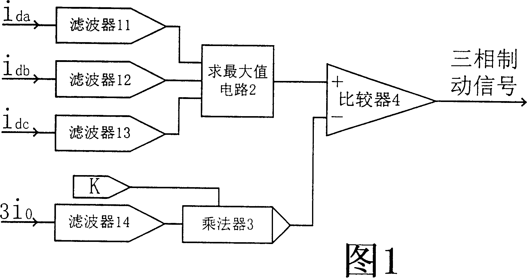
[0008] A maximum differential current braking device to prevent maloperation of transformer differential protection. Its circuit structure is shown in Figure 1. When the signal at the positive input terminal of comparator 4 is smaller than the signal at the negative input terminal, comparator 4 outputs 0, and it is judged as an area If an external ground fault occurs, the outlet of the three-phase differential protection is blocked, otherwise the output of comparator 4 is 1, and the three-phase differential protection is allowed to operate. In the case that the differential current and the zero-sequence current are attributed to the same side and the same transformation ratio, the setting value K is 0.1. The advantage of this device is that when the error of the three-phase current transformer is inconsistent, Y 0 The transformer differential protection maloperation caused by the ground fault outside the side zone does not affect the correct operation of the differential prote...


PUM


Abstract

The invention discloses a maximum differential flow brake device for preventing voltage transformer differential protection unwanted operation, wherein the three-phase difference currents in the transformer differential protection constitute ratio braking element with the zero-sequence current on the Y0 side, the Y0 lateral area outer ground fault is determined, when the ratio of the differential current and the zero-sequence current is smaller than a setting value K, the comparator outputs 0, the lateral area outer ground fault is determined, the three-phase differential protection exit is locked, otherwise the comparator outputs 1, and the corresponding differential protection actuations are allowed. The advantage of the invention is, the transformer differential protection accidental operation resulted from ground fault outside the Y0 lateral area when the errors of the three-phase current transformer are in inconformity without influencing the correct actuation of the differential protection under the circumstance of in-area faults.

Description

technical field [0001] The invention relates to a transformer protection device, in particular to a maximum differential current braking device for preventing maloperation of transformer differential protection. Background technique [0002] The existing power transformer differential protection device uses a ratio brake element, that is, the ratio of the differential current to the through current, to identify the fault outside the zone and the fault in the zone; The waveform or harmonic content of the differential current is used to identify the excitation inrush current and over-excitation current to achieve the purpose of identifying internal faults. to Y 0 / Δ wiring power transformer, in order to prevent Y 0 The zero-sequence current of the ground fault outside the side area causes the differential protection to malfunction. At present, Y 0 The method of transforming the side three-phase current eliminates the influence of zero-sequence current. But when Y 0 The er...

Claims


Application Information

Patent Timeline
Patent Type & Authority Patents(China)
IPC IPC(8): H02H7/045
Inventor 徐习东
Owner ZHEJIANG UNIV
Why Eureka
Try Eureka