
Arrester

A spark gap and resistance technology, which is applied in the field of spark gaps, can solve the problems of increasing the operating voltage of multi-stage spark gaps, and achieve the effect of improving the characteristics of operating parameters.

Inactive Publication Date: 2008-04-02
OBO BETTERMANN GMBH & CO KG
View PDF5 Cites 1 Cited by
  • Summary
  • Abstract
  • Description
  • Claims
  • Application Information

AI Technical Summary

Problems solved by technology

This effect results in an increase in the operating voltage of the multi-stage spark gap with increasing voltage steepness of the voltage to be applied

Method used


Image

  • Arrester

Examples


Embodiment Construction

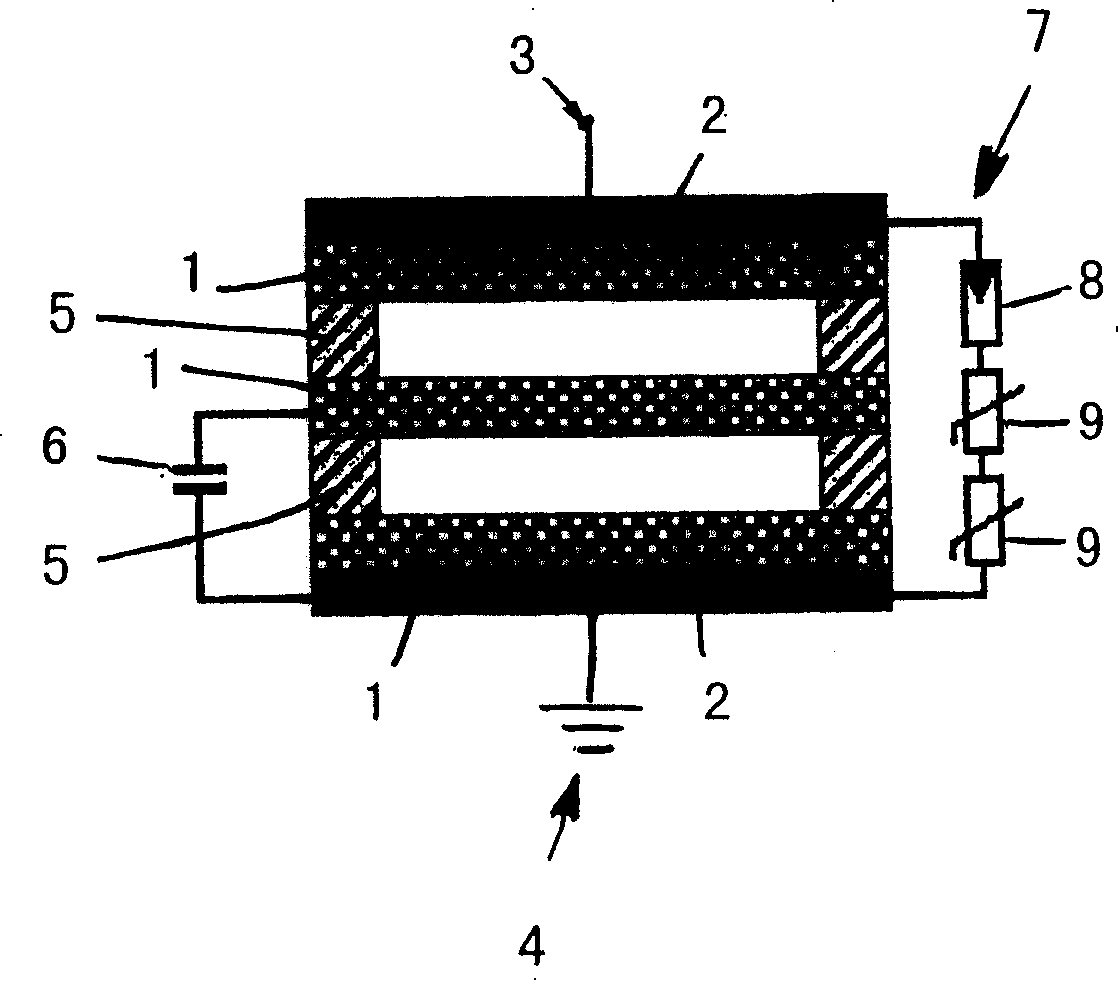
[0019] The multistage spark gap here consists of three graphite electrodes 1 , which are covered at their ends with electrode plates 2 . At 3 a phase connection is provided, and at 4 a junction with a reference potential, preferably ground potential, is provided. Teflon rings 5 ​​are arranged between graphite electrodes 1 made of graphite as insulating elements. This is a spark gap filled with air. In this embodiment, the above-mentioned partial spark gaps are connected through a capacitor 6 except the first spark gap to be activated in the event of an overvoltage accident, and the second spark gap is connected to the common reference potential 4 through the capacitor 6 superior.

[0020] According to the invention, a multistage spark gap consisting of partial spark gaps is connected in parallel with a bypass 7 consisting of an auxiliary spark gap 8 and two varistors 9 connected in series. The auxiliary spark gap 8 here is a spark gap filled with gas, which acts faster than...


PUM


Abstract

The spark clearance has as much possible partial spark clearances connected in series, in particular, these partial spark clearances are wired by capacitor (6) except the first spark clearance reacting in the case of overvoltage phenomenon, and, in particular, the second spark clearance and each spark clearance other than it are connected with common reference electric potential (4), particularly, ground potential through the capacity (6). To markedly improve reaction characteristic of a spark clearance, a bypass (7) composed of an auxiliary spark clearance (8) having a smaller reaction voltage than a reaction voltage of a single spark clearance or these partial spark clearances and at least one varistor (9) is connected in parallel with a multiple spark clearance composed of the single spark clearance or a plurality of partial spark clearances connected in series.

Description

technical field [0001] The invention relates to a spark gap, in particular an N-PE spark gap, preferably with a plurality of partial spark gaps connected in series, in particular, except for the first spark to be activated in the event of an overvoltage accident. All spark gaps are connected via a capacitor, wherein in particular the second and any subsequent spark gaps are connected via this capacitor to a common reference potential, in particular ground potential. Background technique [0002] Such spark gaps are known, for example, from DE 19742302A1 and DE 19755082A1. Also known from an earlier patent application (DE 10114592.6) is a spark gap capable of conducting lightning currents, in which spark gaps, in addition to the first spark gap to operate in the event of a lightning current accident , all partial spark gaps are connected via impedance, especially capacitance, so these partial spark gaps are connected sequentially. A multistage control of the spark gap is po...

Claims


Application Information

Patent Timeline
Patent Type & Authority Patents(China)
IPC IPC(8): H01T4/10F02B23/08H01T2/00H01T4/12H01T4/18H01T4/20H02H9/06H05B41/04
CPCH01T4/20H01T4/18H01T4/12
Inventor J·特林克瓦尔德J·梅佩林克
Owner OBO BETTERMANN GMBH & CO KG
Learn More