Electric machine with box body and rotor

A technology for rotors and boxes, which is applied in the direction of electrical components, electromechanical devices, electric components, etc., and can solve problems such as expensive shafts, stuck shafts, and troublesome ball shafts

Inactive Publication Date: 2008-04-16
BSH BOSCH & SIEMENS HAUSGERAETE GMBH
View PDF6 Cites 0 Cited by
  • Summary
  • Abstract
  • Description
  • Claims
  • Application Information

AI Technical Summary

Problems solved by technology

But the positioning of the ring must be very precise, because if the axial play is zero due to inaccurate positioning, then the shaft may jam
Obviously, the positioning of the ball shaft according to this requirement is complex and therefore expensive

Method used


Image

  • Electric machine with box body and rotor
  • Electric machine with box body and rotor
  • Electric machine with box body and rotor

Examples


Embodiment Construction

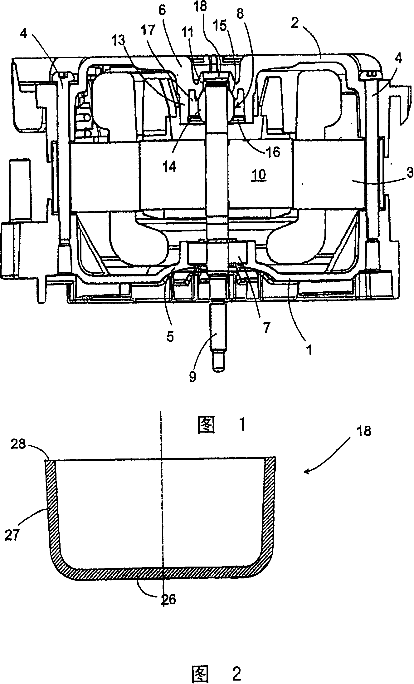
[0021] FIG. 1 shows an axial section through an electric motor according to the invention. The housing of the electric motor consists of a front housing shell 1 , a rear housing shell 2 and a stator lamination 3 . The two plastic injection-molded housing shells 1, 2 are connected by bolts 4 which extend through holes in the rear housing shell 2 and stator laminations 3 and engage in threads in the front housing shell 1 . The box shell 1,2 forms a front or rear bearing cover 5,6 respectively in its middle area, in order to accommodate a bearing 7 or 8, the bearing cover 5,6 is formed respectively, and a shaft 9 of a rotor 10 can be It is rotatably mounted in this bearing 7 or 8 . The shaft 9 extends through the front bearing cap 5 and ends in a journal protruding from the housing where the load is fixed.

[0022] The bearing 7 housed in the front bearing 5 is a ball bearing with an inner ring firmly connected to the shaft 9 and an outer ring firmly connected to the box shell...


PUM


Abstract

The invention relates to an electric machine comprising a housing (1, 2, 3) and a rotor (10). A shaft (9) is rotationally held while retaining axial play in a front (5) and rear (6) end shield of the housing. The axial play of the rotor in one direction is limited by a stop body (18), which is inserted in an axial direction into the rear end shield (6) and which faces an axial end of the shaft (9). The stop body (18) is mounted after the housing has been assembled by displacing the shaft out of a stop position by a desired amount of play ( delta I) and by bringing the stop body into contact with one end of the shaft (9).

Description

technical field [0001] The present invention relates to an electric motor, in particular a low-power to medium-power electric motor, and a method for mounting such a motor. Background technique [0002] According to the conventional design of such an electric machine, the shaft of the rotor is rotatably mounted on the machine housing at two locations, referred to as front bearing caps or rear bearing caps. [0003] If the shaft of the finished motor should not exceed a predetermined clearance in the axial direction, this is achieved by applying ball bearings in the two bearing caps, each of which can have a The required axial clearance is large, and for each bearing one ring is axially fixed on the shaft and the other ring is axially fixed on one of the bearing caps so that the The overlap of the clearances of the two ball bearings is not greater than the allowable clearance of the shaft. However, the positioning of the ring must be very precise, because if the axial play ...

Claims


Application Information

Patent Timeline
IPC IPC(8): H02K7/08H02K5/167
CPCH02K5/1672
Inventor J·科斯特卡J·弗尔利克O·乌斯特曼
Owner BSH BOSCH & SIEMENS HAUSGERAETE GMBH
Why Eureka
Try Eureka