Fixed disc type brake

A disc brake and fixed caliper technology, applied in the direction of brake discs, wheel hubs, vehicle components, etc., can solve the problems of large air passages, high thermal loads, etc.

Inactive Publication Date: 2008-06-11
SAF HOLLAND GMBH
View PDF7 Cites 2 Cited by
  • Summary
  • Abstract
  • Description
  • Claims
  • Application Information

AI Technical Summary

Problems solved by technology

This has the consequence that especially the lubricant and the wheel bearing seals on the brake side are subjected to excessive thermal loads
Therefore, the direct cogging of such a brake disc with the hub body requires a very large ventilation duct, as it is proposed, for example, in EP 0621829B1

Method used


Image

  • Fixed disc type brake
  • Fixed disc type brake
  • Fixed disc type brake

Examples


Embodiment Construction

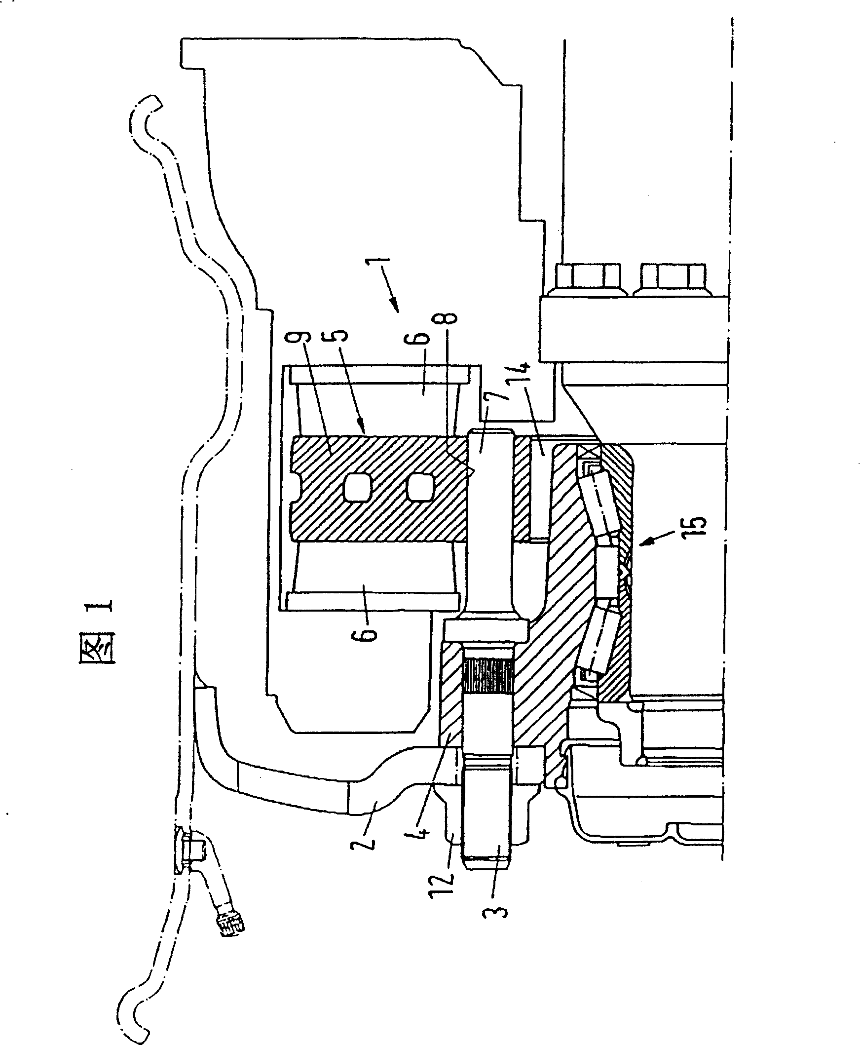
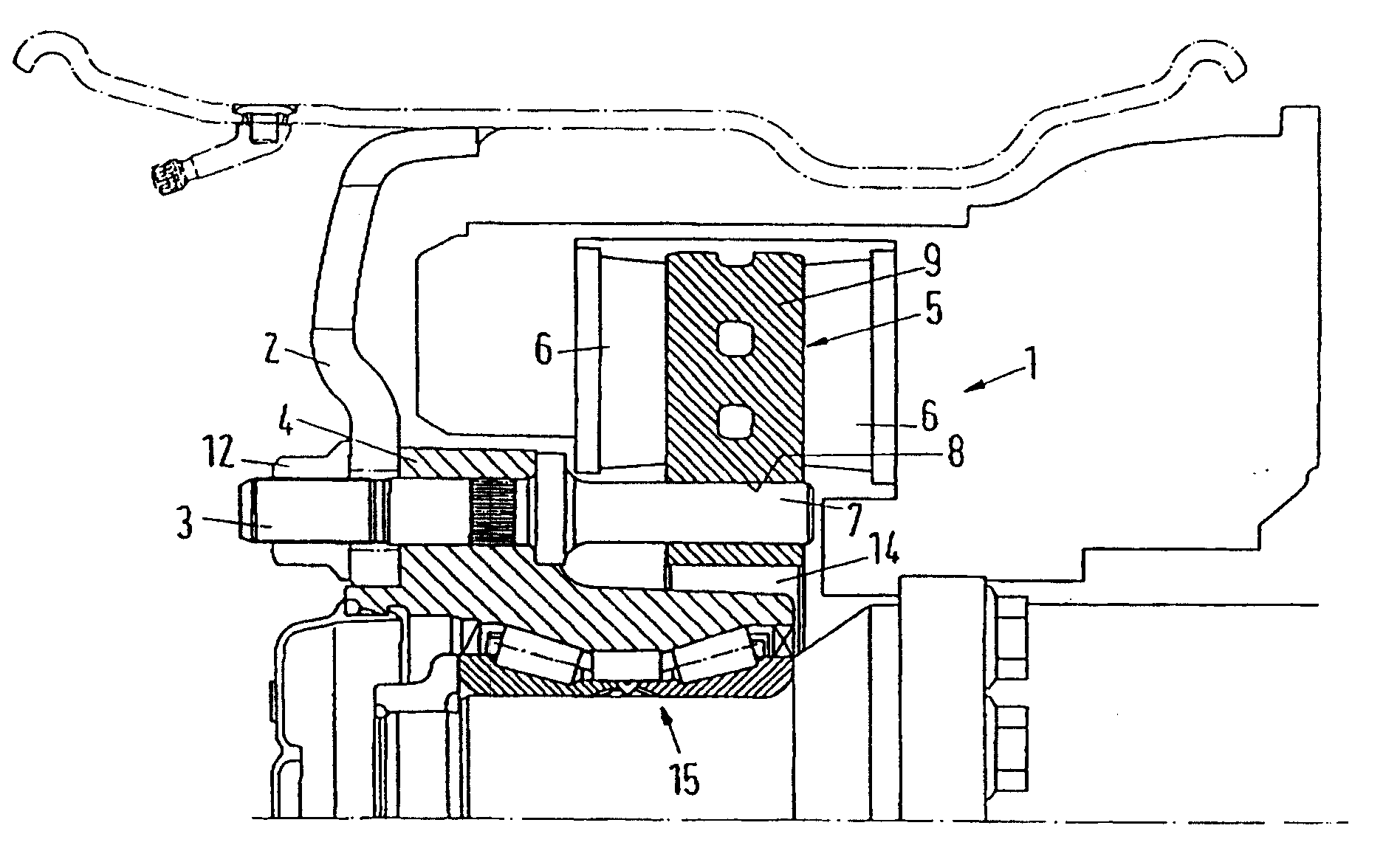
[0019] The fixed-caliper disc brake according to FIG. 1 is specified in particular for commercial vehicles, the wheels 2 of which are fastened to the wheel hub 4 by means of wheel bolts 3 and wheel nuts 12 .

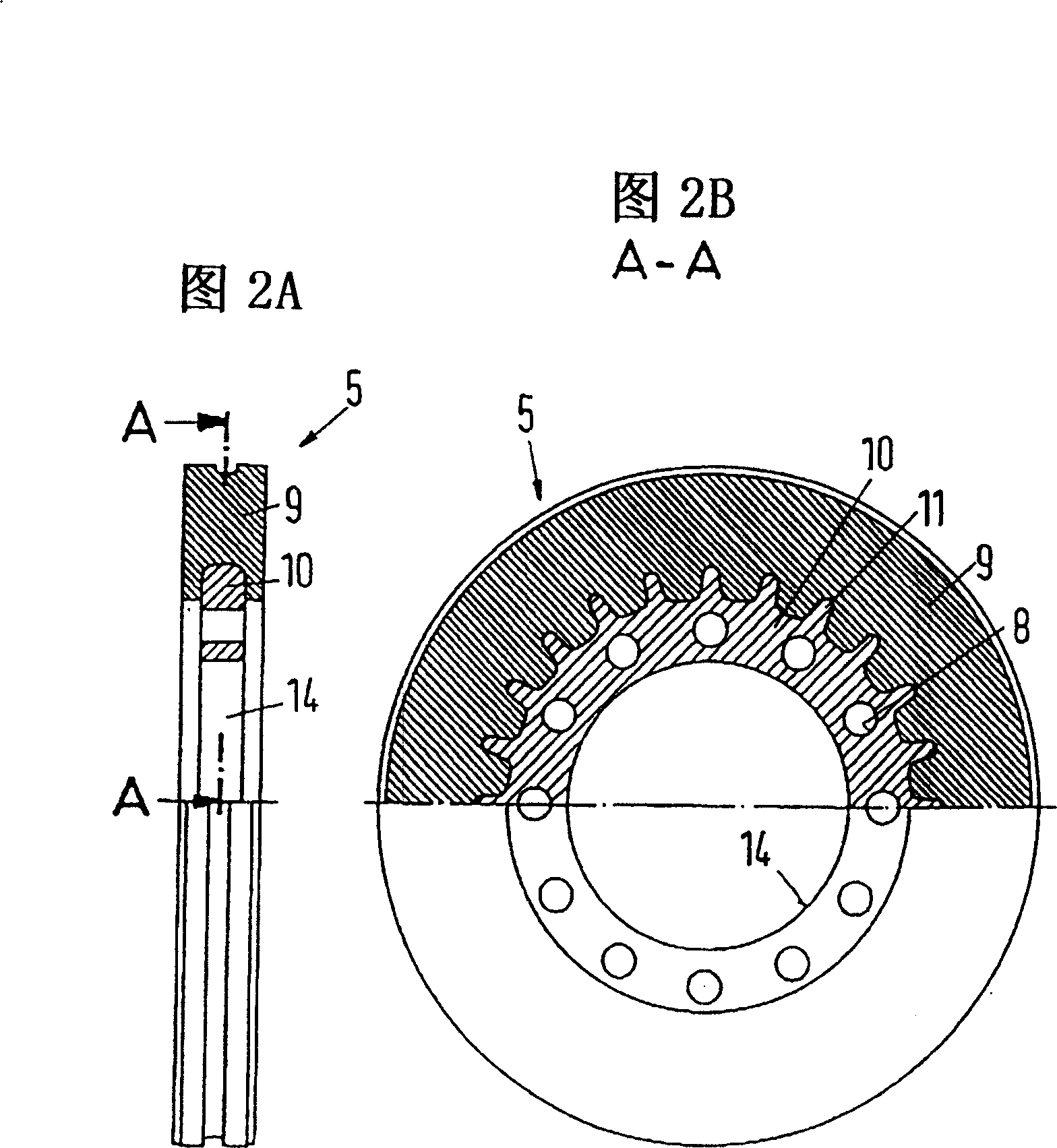
[0020] However, it can be seen in FIG. 1 that the conventional wheel stud 3 is not used, but that the wheel stud has a cylindrical stud extension 7 that is on the other side of a shoulder 13 by means of the shoulder and by means of the wheel. The nut 12 secures the wheel 2 to the hub 4 , and the bolt extension 7 projects into the hole 8 of the brake disc 5 . The screw extension 7 has a slight play in the bore 8 which on the one hand allows a certain thermal expansion of the brake disc 5 relative to the hub 4 at the braking temperature and on the other hand ensures a reliable axial guidance of the brake disc 5 , which is necessary because the brake disc material 9 is increasingly subject to wear during driving of the vehicle.

[0021] The individual brake pads 6 act on t...


PUM


Abstract

The present invention relates to a fixed clamp disk type brake for vehicle, and is characterized by that its every wheel is respectively fixed on the wheel hup by means of every wheel screw bolts, in the zone of wheel hup of brake disk capable of axially shifting is supported, and can be clamped between the brake blocks. According to said invention the brake disk can utilize at least one bolt extended portion toward interior, specially utilize the balt extended portion of wheel self-body to make axial mobile guide relatively to hup. Said invention can use this mode to make simple, low-cost and reliable compensation of wear and tear of the brake disk.

Description

technical field [0001] The invention relates to a disc brake for a vehicle, in particular a commercial vehicle, the wheels of which are respectively fastened to a hub by means of wheel bolts, with an axially displaceable brake mounted in the region of the hub. A disc, which can be clamped between the brake pads, for example hydraulically. Background technique [0002] In fixed caliper disc brakes, the disc must be supported axially displaceable due to increasing pad and disc wear, unlike floating caliper disc brakes with a fixed disc, where The movable pliers are movable. Hydraulically operated fixed caliper disc brakes are known in the field of cars and motorcycles. In this case, the brake disc is mounted movably directly on the hub body via relatively expensive cogs. With fixed-caliper disc brakes for commercial vehicles, such mounting is certainly not possible, since the cogs are arranged directly via the wheel bearings. This has the consequence that in particular the...

Claims


Application Information

Patent Timeline
Patent Type & Authority Patents(China)
IPC IPC(8): F16D65/12B60B27/00
Inventor 奥拉夫·J·德雷维斯约翰·丹特勒
Owner SAF HOLLAND GMBH
Why Eureka
Try Eureka