Glass moulding-shaping device capable of simplifying mounting-dismounting programme

A glass and program technology, applied in glass forming, glass manufacturing equipment, glass pressing, etc., can solve the problems of complex disassembly and assembly procedures of molds, fine-tuning the thickness of glass lens 6 centers, and poor demoulding, etc.

Inactive Publication Date: 2008-06-25
ASIA OPTICAL CO INC
View PDF0 Cites 0 Cited by
  • Summary
  • Abstract
  • Description
  • Claims
  • Application Information

AI Technical Summary

Problems solved by technology

[0005] 1. The inner and outer sleeves 1 and 4 of this kind of mold are usually only processed to the general matching accuracy (about 20×10 -5 m~30×10 -5 m), and the cooperation between the upper and lower mold cores 3, 2 and the inner sleeve 1 will be processed to a relatively precise matching accuracy (about 2-3 μm). In addition, the inner and outer sleeves 1, 4 There is no blocking structure between them. Therefore, before removing the upper mold core 3, if the outer sleeve 4 is not removed first, when the upper mold core 3 is pulled out by the mechanical arm, due to the inner The sleeve 1 is precisely matched with the upper mold core 3, and the inner sleeve 1 is not limited by any structure at the same time, so the inner sleeve 1 will often follow the upper mold relative to the outer sleeve 4. Kernel 3 moves up, resulting in poor demoulding. Accordingly, the forming system must be provided with a first dismantling station 705 and related machinery before the second dismantling station 706 for dismantling the outer sleeve 4. Arm, and then also must be after this first assembly station 708, be used for assembling the second assembly station 709 of this outer sleeve 4 and relevant robot arm in addition, like this, not only can cause the dismounting procedure of this mold to be complicated, It will increase the equipment cost of the forming system
[0006] 2. When the mold is moved between the heating station 701, the first and second pressurization stations 702, 703 and the cooling station 704, since the bottom end of the outer sleeve 4 is directly abutted against these stations other base plates, and will move relative to the other base plates of these stations, therefore, the operator cannot position a gasket (shown at the end of the figure) between the bottom end of the outer sleeve 4 and the other base plates of these stations In this way, the operator cannot fine-tune the central thickness of the formed glass lens 6 by changing the top height of the outer sleeve 4

Method used


Image

  • Glass moulding-shaping device capable of simplifying mounting-dismounting programme
  • Glass moulding-shaping device capable of simplifying mounting-dismounting programme
  • Glass moulding-shaping device capable of simplifying mounting-dismounting programme

Examples


Embodiment Construction

[0017] The aforementioned and other technical contents, features and effects of the present invention will be clearly understood in the following detailed description of the two preferred embodiments with reference to the drawings.

[0018] Before presenting a detailed description, it is noted that in the following description, similar elements are denoted by the same reference numerals.

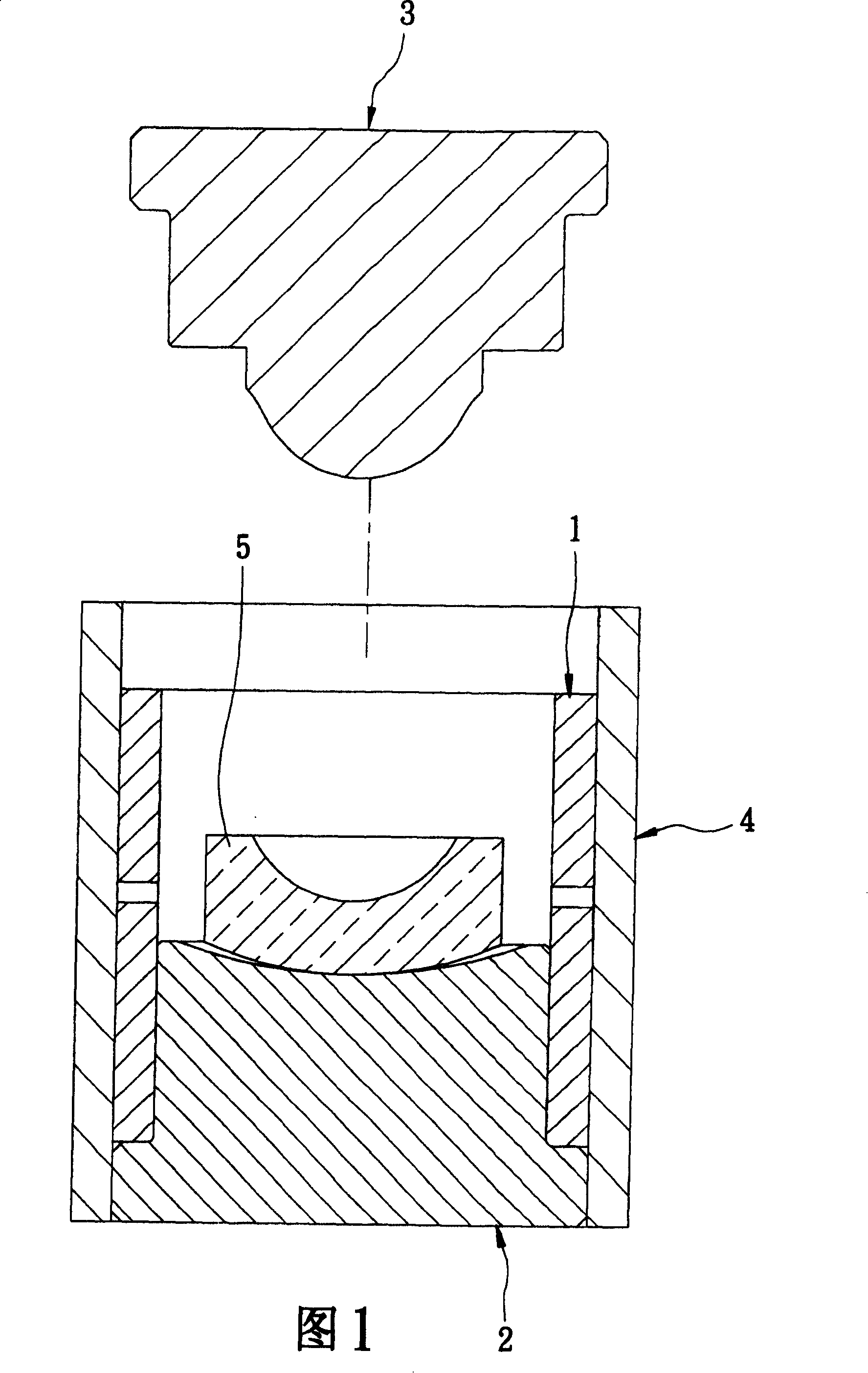
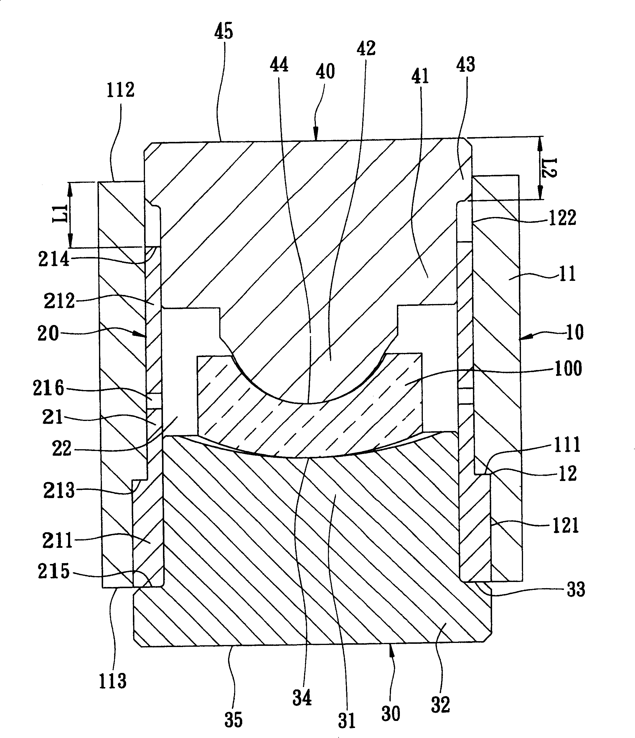
[0019] refer to image 3 , the first preferred embodiment of the glass molding device that can simplify the disassembly procedure of the present invention can be used to form a glass nitrate material 100 with a coefficient of thermal expansion α into a glass lens 200 (see Figures 4 and 5), the The glass molding device includes: an outer sleeve 10 , an inner sleeve 20 , a lower mold core 30 , and an upper mold core 40 .

[0020] The outer sleeve 10 has a first peripheral wall 11 , a first inner hole 12 surrounded and defined by the first peripheral wall 11 , and a first thermal expansion coef...


PUM


Abstract

The invention supplies a glass modeling figuration device that could simplify install and uninstall process. It could model a glass saltpeter material into a glass lens, including an out sleeve, an inner sleeve, lower die kernel, upper die kernel. The second, third, and forth expansion coefficient is less that the first expansion coefficient, and the first perisporium has a first top end face. When the upper die kernel moves to the top end face and flat with it, the glass lens would be formed.

Description

technical field [0001] The invention relates to a forming device, in particular to a glass molding device which can simplify the assembly and disassembly procedure of a continuous glass molding system. Background technique [0002] As shown in Figure 1, it is an existing mold for forming optical glass lenses, which includes an inner sleeve 1, a lower mold core 2 that is sleeved in the inner sleeve 1 and can accommodate a glass material 5. , an upper mold core 3 movably sleeved in the inner sleeve 1 , and an outer sleeve 4 detachably assembled outside the inner sleeve 1 . [0003] As shown in Figure 2, the existing continuous glass molding system for forming optical glass lenses generally includes a forming chamber 7, a heating station 701, a first pressurization station 702, a second pressurization station 703, a Cooling station 704 , a first disassembly station 705 , a second disassembly station 706 , a replacement station 707 , a first assembly station 708 , and a second ...

Claims


Application Information

Patent Timeline
Patent Type & Authority Patents(China)
IPC IPC(8): C03B11/08
CPCC03B11/08C03B2215/48C03B2215/72C03B2215/03
Inventor 王孟坤李蓉家
Owner ASIA OPTICAL CO INC
Why Eureka
Try Eureka