Airflow generating structure and the device thereof

A generation device and airflow technology, applied in the field of airflow generation structure and its application device, can solve the problems of poor air output efficiency, noise and vibration, and reduced service life of axial fans

Inactive Publication Date: 2008-06-25
RISUN EXPANSE
View PDF6 Cites 0 Cited by
  • Summary
  • Abstract
  • Description
  • Claims
  • Application Information

AI Technical Summary

Problems solved by technology

[0008] In the existing fan installation, the air output efficiency of the axial flow fan is poor, and at high speeds, the cutting of the blades and slapping the air will cause noise and vibration problems due to the unsmooth cutting of the wind, which will make the human ear feel uncomfortable, and the blades will vibrate and shake. reduce service life

Method used


Image

  • Airflow generating structure and the device thereof
  • Airflow generating structure and the device thereof
  • Airflow generating structure and the device thereof

Examples


Embodiment Construction

[0097] Please refer to Figure 5 and Figure 6 As shown, the first preferred embodiment of the present invention discloses an air flow generating structure 10 , which includes a hub portion 11 , a setting portion 12 , a plurality of spoilers 13 and a stabilizing ring 14 .

[0098] The hub 11 has a top end 111 and a bottom end 112, the top end 111 is generally convex, the bottom end 112 is concavely provided with a cavity 113, and the cavity 113 is inserted with an outwardly extending rotating shaft 15 ( spindle).

[0099] The setting portion 12 is roughly in the shape of a ring plate, which is integrally formed on the outer edge of the bottom end 112 of the hub portion 11 and extends outward along the radial direction of the hub portion 11. The setting portion 12 faces the hub portion 11. One side forms a setting surface 121 .

[0100] The two surfaces of each spoiler 13 are respectively a convex surface and a concave curved surface, so that its appearance presents a curved...


PUM


Abstract

The present invention relates to one airflow generating structure and the device thereof. The airflow generating structure includes one setting part extending outwards from one end of the hub, and radial interval arranged spoilers in the edge of the setting part and with curved surfaces and inclined outside edge. The spoilers form a range greater than the setting part. Air is sucked in the end of the hub far from the setting part, made to flow to the other end, and blown out through the edge of the setting part.

Description

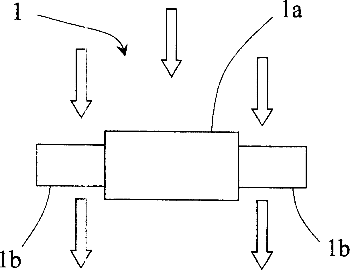
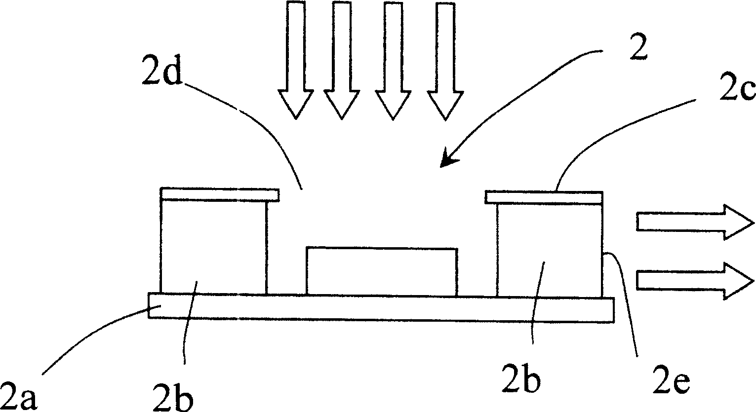
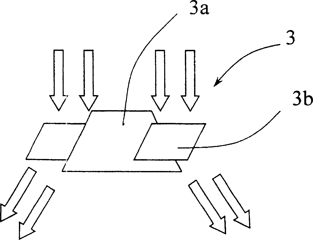
technical field [0001] The invention relates to a fan, in particular to a quiet and large air flow generating structure and its application device. Background technique [0002] The function of the fan is mainly used to forcibly drive the gas flow, thereby generating a forced convection effect (forced convection). Generally speaking, the air intake direction of the fan is parallel to the rotation axis of the fan impeller, and the air is sucked in along the rotation axis, and then further pushed by the blades to release the air. The air outlet direction is related to the geometric structure of the impeller. Please refer to Figure 1A to Figure 1C , the geometric structure of the fan impeller (impeller), according to the relative relationship between air intake and air outlet, can be divided into three categories: axial flow fan 1 (axial-flow fan), cross-flow fan 2 (radial-flow fan) and oblique flow Fan 3 (diagonal-flow fan). [0003] Please refer to figure 2 combined with...

Claims


Application Information

Patent Timeline
Patent Type & Authority Patents(China)
IPC IPC(8): F04D29/66F04D29/26F04D25/08
Inventor 黄江城孙建中
Owner RISUN EXPANSE
Why Eureka
Try Eureka