
Base assembly for flat display and assembling method thereof

A flat-panel display and flat-panel display technology, applied in the direction of instruments, optics, electrical components, etc., can solve problems such as unusable, waste of materials, installation and disassembly, and difficulty

Inactive Publication Date: 2008-06-25
AU OPTRONICS CORP
View PDF10 Cites 0 Cited by
  • Summary
  • Abstract
  • Description
  • Claims
  • Application Information

AI Technical Summary

Problems solved by technology

This not only requires additional tools and time to disassemble the iron shell, but also, the deformation of the iron shell is permanent deformation, so it can no longer be used, resulting in waste of materials and difficulty in installation and disassembly

Method used


Image

  • Base assembly for flat display and assembling method thereof
  • Base assembly for flat display and assembling method thereof
  • Base assembly for flat display and assembling method thereof

Examples


Embodiment Construction

[0021] In order to illustrate the technical content of the present invention more clearly, the following preferred specific embodiments are specially cited as follows.

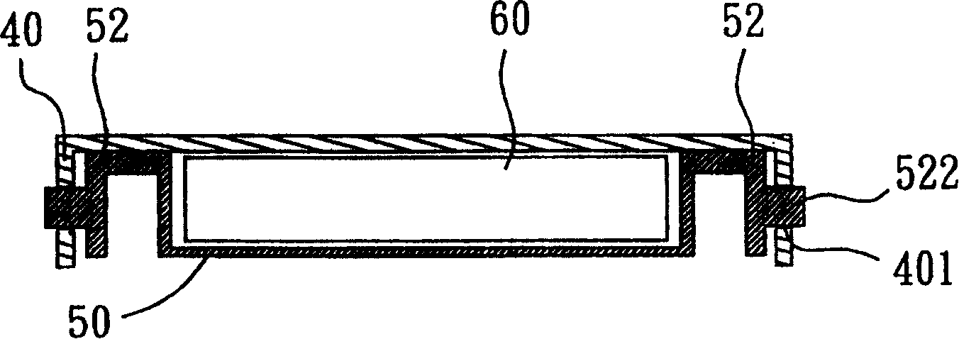
[0022] Please refer to FIG. 2(A), which is a cross-sectional view of a liquid crystal display device according to a preferred embodiment of the present invention. When the liquid crystal display panel module 60 is covered and fixed between the top case 40 and the main frame body 50, the main frame body 50 is locked with the top case body 40 by means of the joint unit 52 on its edge, and a backlight module. The coupling unit 52 includes a fastening portion 522 , and the fastening portion 522 can just be locked with the pre-aligned opening 401 formed on the periphery of the top case 40 . When it is desired to disassemble and separate the top case 40 from the main frame body 50, please refer to FIG. Breaking away from the opening 401 , the top case 40 and the main frame body 50 can be disassembled and separated...


PUM


Abstract

This invention relates to a base socket set of a plane display, which is to contain and fix a plane display panel module. It mainly comprises a main frame located on one side of the plane display panel module used to contain and fix the module; a top shell with multiple small holes used to combine with the main frame and to cover and fix the plane display panel module, wherein, the open holes on the shell are located on periphery of the shell; multiple combination units with at least one locking part located one periphery of the shell used to fix the open hole of the top shell through locking part and to control the connection and separation between the locking part and open holes on the shell to cover and fix the plane panel module.

Description

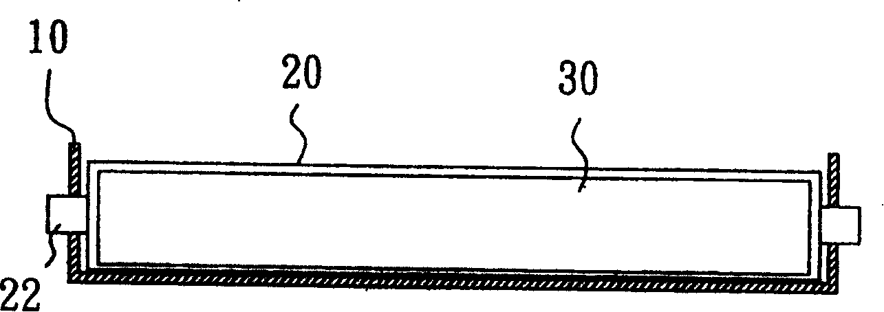
technical field [0001] The invention relates to a structure for a flat display, in particular to a base set for a flat display. The invention also relates to its assembly method. Background technique [0002] In the past, the casing of the flat-panel display is composed of metal and plastic, so that the flat-panel display module, such as the liquid crystal display module 30 , is assembled and fixed. Referring to FIG. 1(A), the iron case 10 and the plastic frame 20 are fixed by a tenon 22 to assemble the liquid crystal display module 30 therebetween. But when the liquid crystal display module 30 is to be repaired, tools must be used to deform the iron case 10 and pry it open, as shown in FIG. This not only requires extra tools and time to disassemble the iron shell, but also, the deformation of the iron shell is permanent, so it cannot be used again, resulting in waste of materials and difficulty in installation and disassembly. [0003] The industry and the market urgentl...

Claims


Application Information

Patent Timeline
Patent Type & Authority Patents(China)
IPC IPC(8): G02F1/1333H05K5/00
Inventor 刘子谊
Owner AU OPTRONICS CORP
Learn More