Display device

Inactive Publication Date: 2021-12-30
WUHAN CHINA STAR OPTOELECTRONICS SEMICON DISPLAY TECH CO LTD
View PDF8 Cites 0 Cited by
  • Summary
  • Abstract
  • Description
  • Claims
  • Application Information

AI Technical Summary

Benefits of technology

[0015]The present invention provides a display device to replace at least one convex lens with the plano-convex lens which is half as thick as the convex lens to reduce the overall thickness of the camera module. Thus, a space below the display device enables to meet the installation of the camera m

Problems solved by technology

Due to a large thickness of the convex lens, the camera

Method used


Image

  • Display device
  • Display device
  • Display device

Examples


Example

The First Embodiment

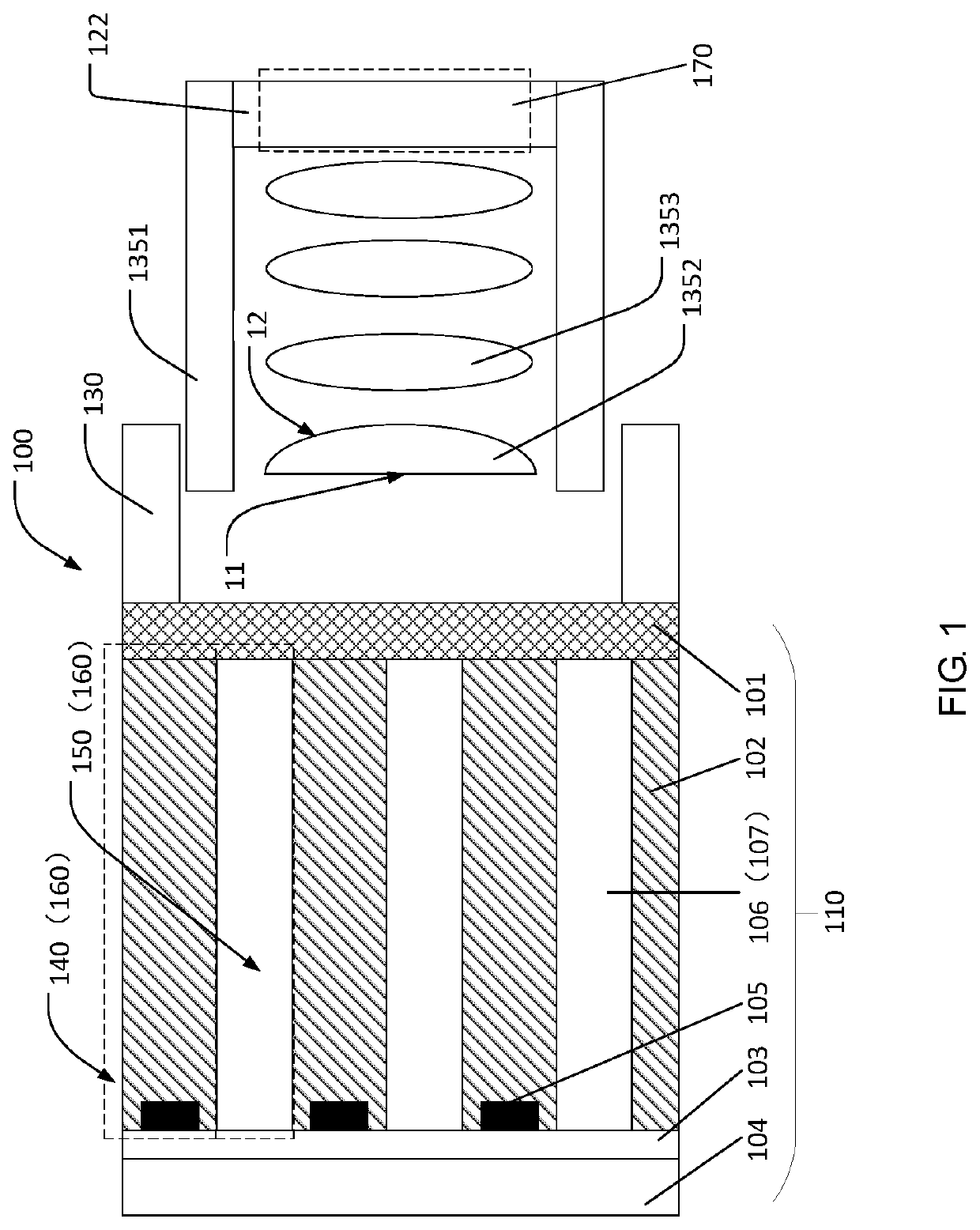
[0024]As shown in FIG. 1, in a first embodiment, it provides a display device 100 including a display panel 110, a camera module 120, a frame and a back plate 140.

[0025]The display panel includes a transparent substrate 101, an array substrate 102, a thin film encapsulation layer 103 and a glass cover 104.

[0026]Material of the transparent substrate 101 includes, but is not limited to, polyimide, diphenylene ether resin or polyethylene naphthalate. The present invention is mainly to form a transparent film layer by coating the polyimide on a rigid load to be the transparent substrate 101. The transparent substrate 101 has a higher stretchability to serve as the material for manufacturing the flexible display panel 110. The rigid load is generally detached after the flexible display panel 110 manufactured.

[0027]The array substrate 102 is disposed on the transparent substrate 101 and has a display zone 160 with sub-pixel areas 140 and non-pixel areas 150 located bet...

Example

The Second Embodiment

[0044]In order to reduce the thickness of the camera module to meet the requirement of the installation space and simultaneously meet different focusing designs, it is also possible to adopt following methods to reduce the entire thickness of the lens assembly 125.

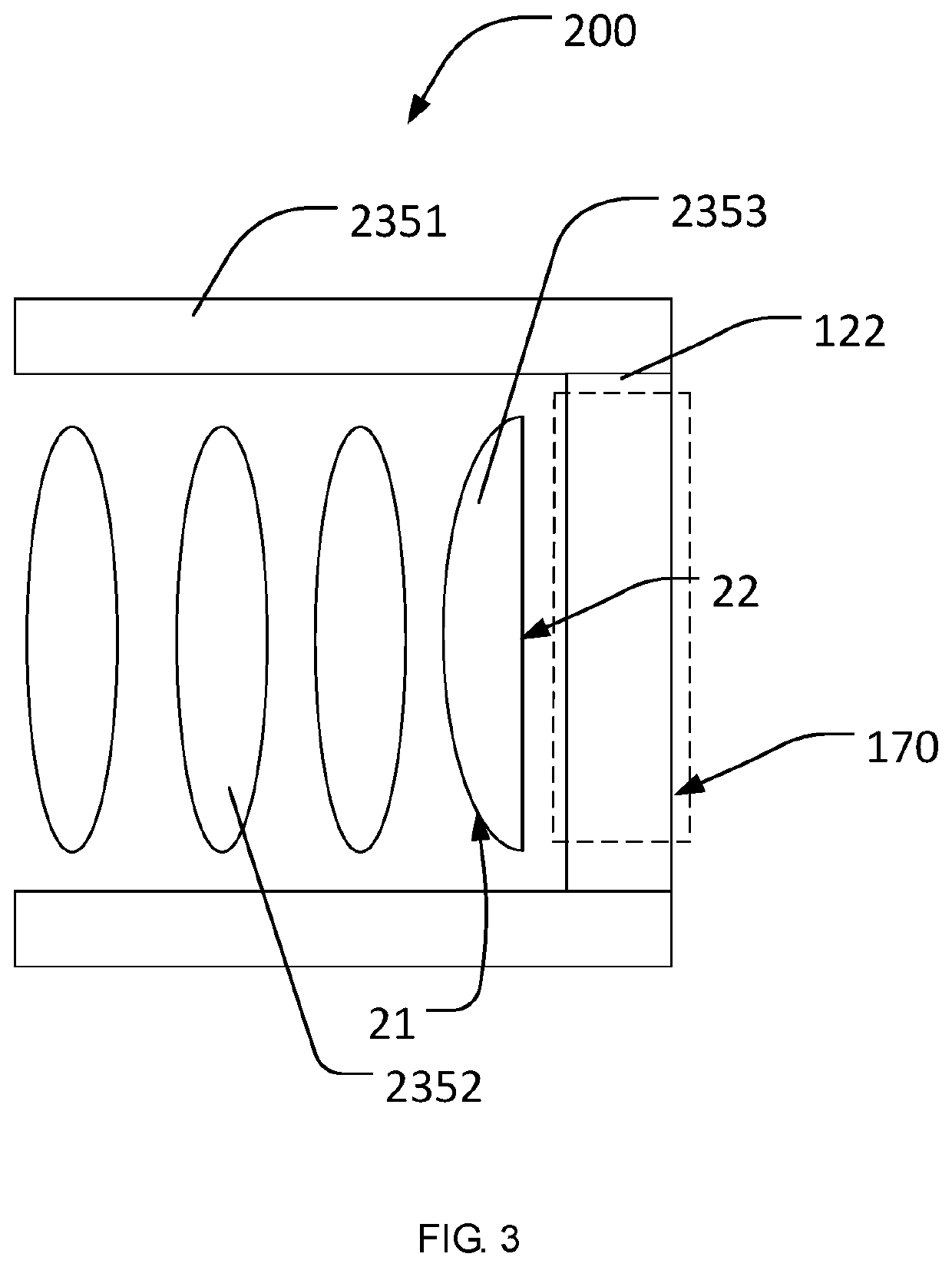
[0045]In the second embodiment, as shown in FIG. 3, the lens assembly includes a second plano-convex lens 2353, at least one second convex lens 2352 and a lens housing 2351. Wherein a number of the second convex lens 2353 is three, and may be one, two, or four.

[0046]The second plano-convex lens 2353 has a second light-in surface 21 being a curved surface toward the light-transmitting zone 107 and a second light-out surface 22 being a flat surface toward the image sensor 122.

[0047]The second embodiment with respect to the first embodiment substantially has identical structures except for the different structure of the camera module. Therefore, it is no longer to describe the structures or components exc...

Example

The Third Embodiment

[0050]In order to further thin the camera module 120, it is also possible to adopt following methods to thin the thickness of the lens of the lens assembly close to the image sensor 122. That is described in the third embodiment.

[0051]As shown in FIG. 4, in the third embodiment, the lens assembly includes a third plano-convex lens 3352, a fourth plano-convex lens 3354, at least one third convex lens 3353 and a lens housing 3351. Wherein a number of the third convex lens 3352 is two, and may be one, three, or four.

[0052]The third plano-convex lens 3352 has a third light-in surface 35 being a flat surface toward the light-transmitting zone as well as a third light-out surface 36 being a curved surface toward the image sensor 122; and the fourth plano-convex lens 3354 with a fourth light-in surface 37 being a curved surface toward the third plano-convex lens as well as a fourth light-out surface 38 being a flat surface toward the image sensor. The third convex lens ...


PUM


Abstract

A display device includes a display panel having a light-transmitting zone; and a camera module including a lens assembly and an image sensor. The camera module is disposed below the display panel and corresponds to the light-transmitting zone. The lens assembly is disposed between the image sensor and a bottom side of the display panel, and the lens assembly has at least one lens, and at least one lens of the lens assembly is a plano-convex lens. It is provided to thin the lens within the prior camera module, and to arrange the lens in the lens assembly. That is able to effectively reduce a thickness of the lens assembly, and eventually make the camera module occupy a smaller space.

Description

FIELD OF INVENTION[0001]The present invention relates to the field of liquid crystal display techniques. In particular, the present invention relates to a display device.BACKGROUND OF INVENTION[0002]Since current mobile phones tend to be light-thin, deformable and full-screen, one way to have a full screen is to hide a camera module within a panel. In order to ensure that the camera module is able to receive more light, there is a high requirement for transmittance of the stack of the panel.[0003]Because of emergence of a screen concept, requirements corresponding high requirements have also arisen with development of technology. The camera module within a current display device consists of convex lenses. Due to a large thickness of the convex lens, the camera module within the display device occupies a larger space.Technical Problem[0004]An object of the present invention is to thin the convex lens within a lens assembly, thereby solving a problem that the camera module occupies th...

Claims


Application Information

Patent Timeline
IPC IPC(8): G02B13/00G02B3/02G02B7/02
CPCG02B13/001G02B2003/0093G02B7/021G02B3/02H04M1/02H04N23/00
Inventor ZHENG, MINKIM, MUGYEOMZHAO, YONG
Owner WUHAN CHINA STAR OPTOELECTRONICS SEMICON DISPLAY TECH CO LTD
Why Eureka
Try Eureka