Fan mechanism

A fan and fan frame technology, applied in the field of fan mechanism, can solve problems such as weak assembly, loud noise, and easy generation of gaps

Inactive Publication Date: 2008-07-23
ASIA VITAL COMPONENTS SHENZHEN CO LTD
View PDF4 Cites 0 Cited by
  • Summary
  • Abstract
  • Description
  • Claims
  • Application Information

AI Technical Summary

Problems solved by technology

[0004] When the heat dissipation fan 12 is activated, the traction fluid enters from the air inlet 131 side of the adapter device 13, and then blows to the heating element 11 on the air outlet 132 side of the adapter device 13 to generate heat dissipation, but this operation mode There is a problem in its implementation. When using the adapter device 13, due to the need to use adhesive or buckle connection methods, the procedure is complicated, so that the indirect composition of the heating element 11, the cooling fan 12, and the adapter device 13 It is not easy to be firm and easy to produce gaps, causing the fluid to overflow fro

Method used


Image

  • Fan mechanism
  • Fan mechanism
  • Fan mechanism

Examples


Embodiment Construction

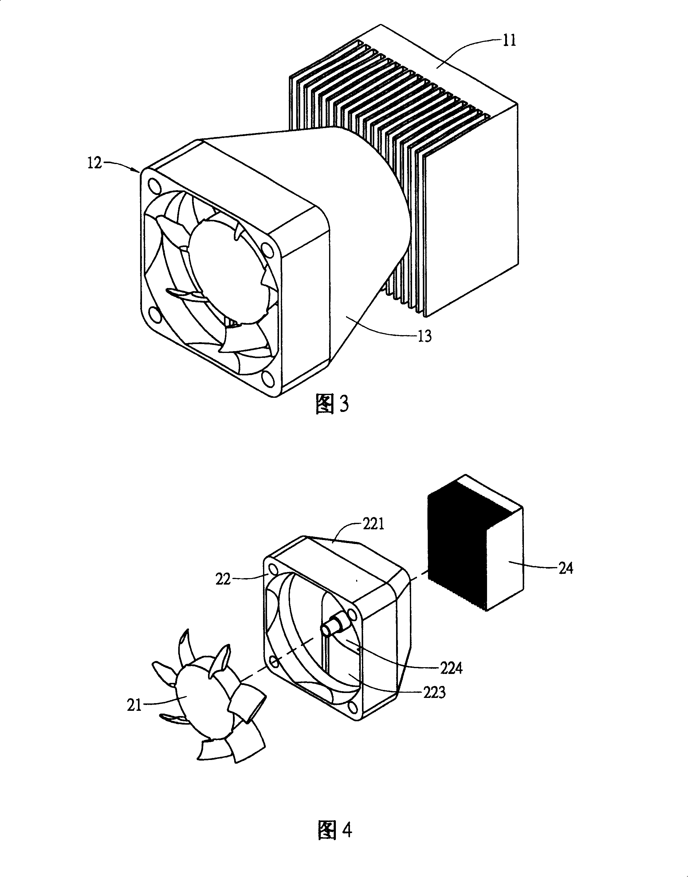
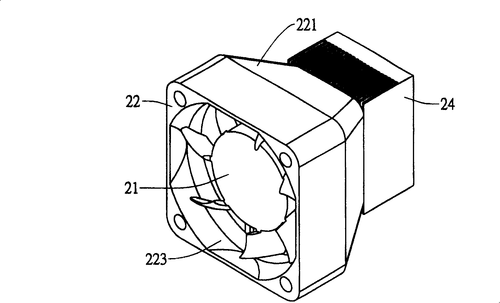
[0025] The present invention provides a fan mechanism, please refer to Figure 4, Figure 5 , Figure 6 The preferred embodiment of the present invention shown, as shown in the figure, at least includes a fan frame 22 and a fan wheel 21, wherein one side of the fan frame 22 is appropriately extended toward the center of the other side to form a tapered There is a tapered part 221, so that the tapered part 221 forms an air outlet 222 that is equal to the area of ​​the heating element 24, and one side of the fan frame 22 is provided with an air inlet 223, and a hub seat 224 is provided in it to pivot the fan. wheel 21, and then the air outlet 222 of the fan frame 22 is connected to the heating element 24, and then the fan frame 22 and the fan wheel 21 which are larger than the area of ​​the heating element 24 are connected to the heating element 24.

[0026] When the fan wheel 21 rotates, the guiding fluid enters through the air inlet 223 and blows to the heating element 24 of th...


PUM


Abstract

The invention discloses a structure of fan and includes frame of fan larger than the area of heat groupware and wheel of fan. The pivot of the wheel of fan is set in the frame of fan and one side of the frame of the fan extend outsides from the center to the edge, forms the uptake equivalent or slightly smaller than the area of heat groupware, sets the frame of fan and wheel of fan larger than the area of heat groupware on the heat groupware, makes the air flow to the heat groupware through the part, increases the thermolysis effect greatly, eliminates the noise and prevents the pressure relief.

Description

technical field [0001] The invention relates to a fan mechanism, in particular to a fan frame structure on a radiator. Background technique [0002] When performing traditional heat dissipation treatment on a heat-generating electronic component, the general processing method is to install a heat-generating component on the electronic component, and set a heat-dissipating fan on the heating component to generate air flow and accelerate the removal of heat from the electronic component. , but due to the fixed limitation of production specifications, when there is a need to enhance heat dissipation, the entire set of heating components and cooling fans must always be replaced, and it is impossible to directly replace a larger cooling fan on the original heating component for heat dissipation. And cause inconvenience and trouble in application. [0003] Please refer to Fig. 1 to Fig. 3, comprise a heating element 11 and a heat dissipation fan 12, wherein the area of ​​this hea...

Claims


Application Information

Patent Timeline
IPC IPC(8): F04D29/54
Inventor 张柏灏刘文豪林志远
Owner ASIA VITAL COMPONENTS SHENZHEN CO LTD
Why Eureka
Try Eureka